14
Array Design
Creating an effective array with the MSL-4 requires a precise
understanding of how to combine the coverage area and SPL
of the individual speaker with those of adjacent speakers.
Array design is a trade-off between increasing on-axis power
and creating smooth transitions between the coverage areas of
adjacent speakers.
As the splay angle (the angle between adjacent cabinet faces)
decreases below the coverage angle of the individual speaker,
the on-axis power increases, but the coverage overlap between
adjacent speakers causes comb filtering and other frequency
response variations.
As the splay angle increases toward the coverage angle, the
on-axis power decreases, but the variations in frequency
response diminish. As the splay angle increases beyond the
coverage angle, noticeable gaps begin to form in the array’s
coverage area.
NOTE: The trapezoidal shape of the MSL-4 determines only
the narrowest recommended splay angle (15°) for horizontal
arrays and does not represent the horizontal coverage area.
A series of outdoor tests was conducted at Meyer Sound
Laboratories to determine coverage angles and on-axis SPL
for arrays with one and two horizontal rows of up to six speak-
ers each, at numerous splay angles. The measurements were
conducted at a distance of 8 m with half-space loading; on-axis
SPL values were interpolated from 8 m to 1 m. The coverage
angle for the array is the result of averaging the –6 dB points
from 125Hz to 8kHz.
The horizontal angles in the tables on the next page represent
the optimal narrow (15°), middle (22.5°), and wide (30°) orien-
tations for the MSL-4. The 10° and 20° vertical splay angles
represent the optimal narrow and wide vertical configurations.
2@0° LT denotes long throw: the two horns are coupled directly
together (top speaker upside down/bottom speaker upright) to
form a single narrow horn.
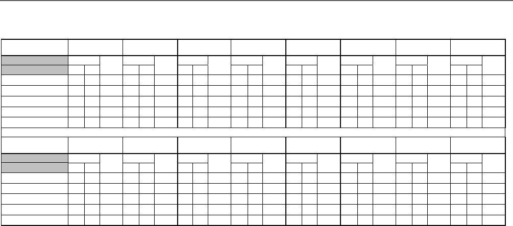
The following tables show the SPL and coverage areas that
result from grouping the MSL-4 in arrays of up to six units
horizontally and two rows vertically. If this information does
not address your application requirements, contact Meyer Sound
to obtain additional information on array design.
MSL-4 Array Coverage and Maximum SPL Chart
Horizontal Units &
Angle 1 2 @ 15 ° 2 @ 22.5° 2 @ 30° 3 @ 15° 3 @ 22.5° 3 @ 30 ° 4 @ 15°
Coverage
Max
SPL
(dB Pk)
Coverage
Max
SPL
(dB Pk)
Coverage
Max
SPL
(dB Pk)
Coverage
Max
SPL
(dB Pk)
Coverage
Max
SPL
(dB Pk)
Coverage
Max
SPL
(dB Pk)
Coverage
Max
SPL
(dB Pk)
Coverage
Max
SPL
(dB Pk)H V H V H V H V H V H V H V H V
Vertical Rows & Angle
1 40° 35° 140 20° 35° 145 50° 35° 143 70° 35° 141 55° 35° 147 80° 35° 146 100° 35° 146 70° 35° 149
2 LT (0°) 40° 20° 146 20° 20° 151 50° 20° 149 70° 20° 147 55° 20° 153 80° 20° 152 100° 20° 152 70° 20° 155
2 @ 10° 40° 40° 145 20° 40° 150 50° 40° 148 70° 40° 146 55° 40° 152 80° 40° 151 100° 40° 151 70° 40° 154
2 @ 20° 40° 55° 144 20° 55° 149 50° 55° 147 70° 55° 145 55° 55° 151 80° 55° 150 100° 55° 150 70° 55° 153
Horizontal Units &
Angle 4 @ 22.5° 4 @ 30° 5 @ 15° 5 @ 22.5° 5 @ 30° 6 @ 15° 6 @ 22.5° 6 @ 30°
Coverage
Max
SPL
(dB Pk)
Coverage
Max
SPL
(dB Pk)
Coverage
Max
SPL
(dB Pk)
Coverage
Max
SPL
(dB Pk)
Coverage
Max
SPL
(dB Pk)
Coverage
Max
SPL
(dB Pk)
Coverage
Max
SPL
(dB Pk)
Coverage
Max
SPL
(dB Pk)H V H V H V H V H V H V H V H V
Vertical Rows & Angle
1 100° 35° 148 130° 35° 147 95° 35° 150 120° 35° 147 160° 35° 146 100° 35° 150 145° 35° 148 185° 35° 147
2 LT (0°) 100° 20° 154 130° 20° 153 95° 20° 156 120° 20° 153 160° 20° 152 100° 20° 156 145° 20° 154 185° 20° 153
2 @ 10° 100° 40° 153 130° 40° 152 95° 40° 155 120° 40° 152 160° 40° 151 100° 40° 155 145° 40° 153 185° 40° 152
2 @ 20° 100° 55° 152 130° 55° 151 95° 55° 154 120° 55° 151 160° 55° 150 100° 55° 154 145° 55° 152 185° 55° 151


