


6
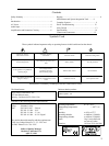
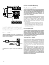
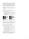
Power Connector Wiring
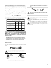
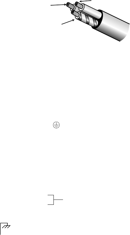
Use the following AC cable wiring diagram to create interna-
tional or special-purpose power connectors:
brown = hot
blue =
neutral
yellow/green =
earth ground
(chassis)
AC cable color code
If the colors referred to in the diagram don't correspond to the
terminals in your plug, use the following guidelines:
• Connect the blue wire to the terminal marked with an
N or colored black.
• Connect the brown wire to the terminal marked with an
L or colored red.
• Connect the green and yellow wire to the terminal marked
with an E (or ) or colored green (or green and yel-
low).
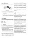
Audio Input
The MSL-4 presents a 10 kΩ balanced input impedance to a three-
pin XLR connector wired with the following convention:
Pin 1 — 220 kΩ to chassis and earth ground (ESD clamped)
Pin 2 — Signal
Pin 3 — Signal
Case — Earth (AC) ground and chassis
Shorting an input connector pin to the case can form a ground
loop and cause hum.
Pins 2 and 3 carry the input as a differential signal; their polar-
ity can be reversed with the input polarity switch on the user
panel. If the switch is in the up position, pin 2 is hot relative
to pin 3, resulting in a positive pressure wave when a positive
signal is applied to pin 2. Use standard audio cables with XLR
connectors for balanced signal sources.
TROUBLESHOOTING NOTE: If abnormal noise (hum,
hiss, popping) is produced from the loudspeaker, disconnect
the audio source from the speaker. If the noise stops, then the
problem is not within the loudspeaker; check the audio input
and AC power.
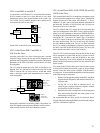
A single source can drive multiple MSL-4s with a paralleled
input loop, creating an unbuffered hardwired loop connection.
The input impedance fo a single MSL-4 is 10kΩ; cascading
n MSL-4s will produce a balanced input impedance of 10kΩ
divided by n. To avoid distortion from the source, make sure
that the source equipment can drive the total load impedance
presented by the paralleled input circuit. For most source
equipment it is safe to drive circuits whose input impedance
is no smaller than 10 times its output impedance. For example,
cascading 10 MSL-4s produces an input impedance of 1000
Ohms (10kΩ divided by 10). The source equipment should
have an output impedance of 100 ohms or less.
This is also true when connecting in parallel (loop out) MSL-
4s to 650-Ps, DS-4Ps, or any other Meyer Sound self-powered
loudspeaker system.
The LD-1A is highly recommended when driving systems
using multiple speakers. (See Measurement and Integration
Tools, page 9.)
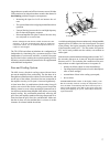
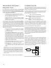
Amplification and Protection Cir-
cuitry
Each driver in the MSL-4 is powered by one channel of the
Meyer Sound MP-2, a 1240W RMS amplifier (620W RMS/ch)
utilizing complementary power MOSFET output stages (class
AB/H). The following sections discuss the MP-2’s limiting
circuitry and the two-fan cooling system.
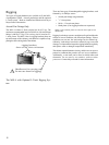
TruPower™ Limiting System
Conventional limiters assume that the resistance of a loudspeaker
remains constant and set the limiting threshold by measuring
voltage only. This method is inaccurate because the loudspeaker’s
resistance changes in response to the frequency content of the
source material and thermal variations in the loudspeaker’s
voice coil and magnet. Conventional limiters begin limiting
prematurely, which under-utilizes system headroom and deprives
the loudspeaker of its full dynamic range.
The TruPower limiting (TPL) system accounts for varying
loudpeaker impedance by measuring current, in addition
to voltage, to compute the power dissipation and voice coil
temperature. TPL improves performance during limiting by al-
lowing the loudspeaker to produce its maximum SPL across its
entire frequency range and extends the lifetime of the drivers
by controlling the temperature of the voice coil.
HI Limit and LO Limit LEDs on the user panel indicate TPL
activity for the high and low frequency amplifier channels. When
either channel exceeds the safe continuous power level, its limiter
engages, ceasing operation when the power level returns to normal.
The limiters for each channel function independently and do
not affect the signal when the LEDs are inactive.
The MSL-4 performs within its acoustical specifications and
operates at a normal temperature if the limit LEDs are on for no
Differential Inputs