


9
3. Carefully raise load block to upper limit and observe if it
stops automatically at desired level.Do not allow load block
to run into hoist housing — this will damage the hoist.
Maintain a minimum clearance of 2" from the hoist housing
and the top of the load block on single-chained models and
1" from the chain support to the top of the load block on
double-chained models.
4. Carefully lower load block to lower limit and observe if it
stops automatically at the desired level.Do not allow slack-
end loop of chain to become taut against hoist housing.This
will damage the hoist.There should be a minimum clearance
of 1½" between the chain stop and the bottom of the hoist.
5. If upper and lower limits operate satisfactorily, hoist is ready
for use. If they are not as desired, repeat adjustment.
BRAKE
Properly adjusted, this brake will release promptly when
energized. It is capable of both smoothly stopping and securely
holding the rated capacity of the hoist. If the hoist develops
either undesirable over-travel after the pushbutton is released
(this condition is most noticeable in the lowering direction) or
hesitates to lift the load promptly when the pushbutton is
depressed (this condition is most noticeable in the hoisting
direction), the brake should be adjusted.
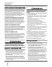
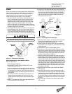
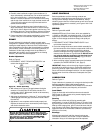
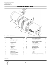
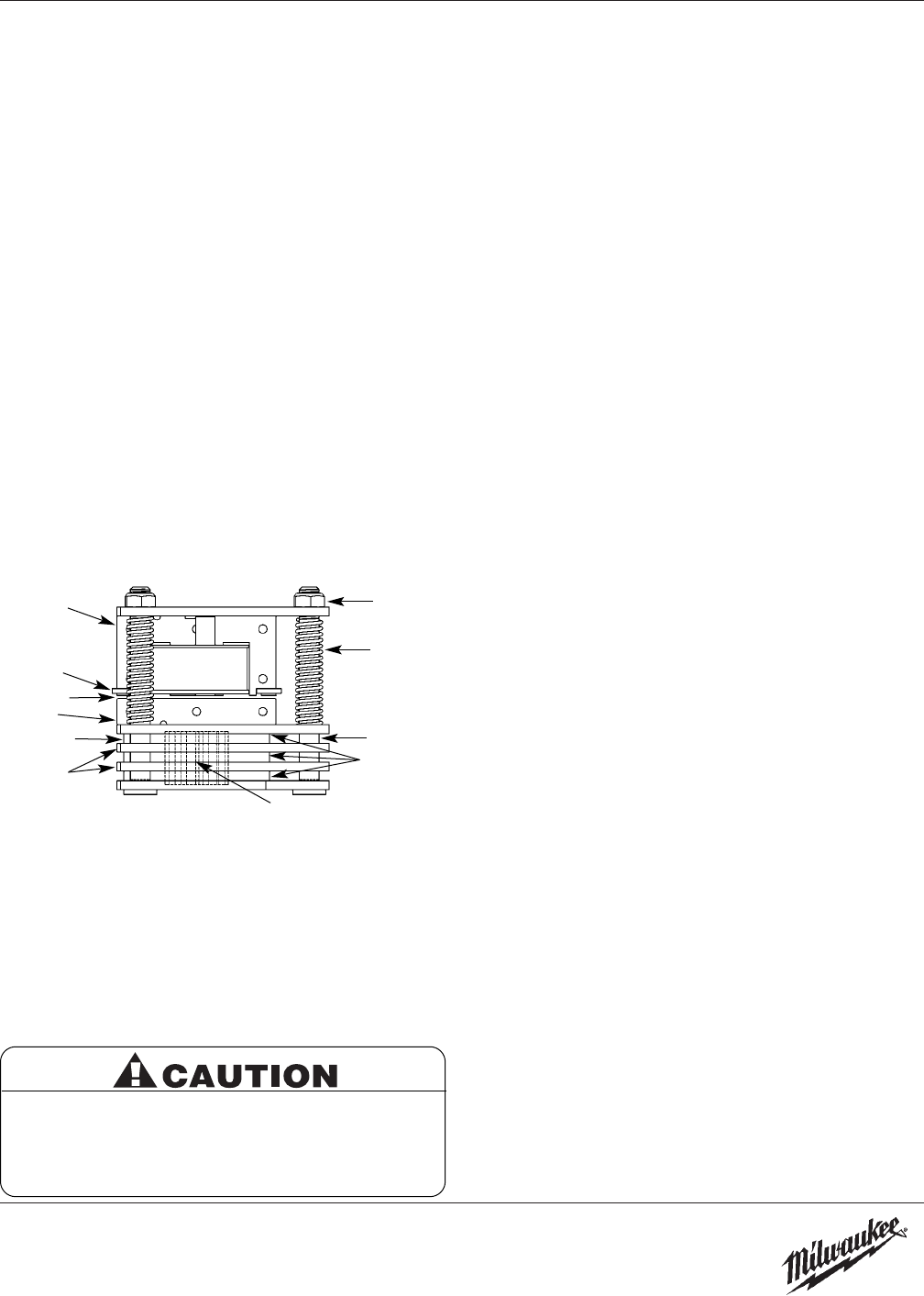
Brake Adjustment
Refer to Figure 6.
1. DISCONNECT HOIST FROM POWER SUPPLY and
remove the electrical cover.
2. With reference to Figure 6, the gap between the brake
armature “A” and the field “B” should be checked.The
correct gap is 0.015". Adjustment should not be necessary
until gap reaches 0.040".
3. Adjust gap by adjusting the 3 locknuts “F” and checking with
a feeler gauge to be sure gap is the same on both ends of
the solenoid.
4. Adjustment is now complete and the brake properly set.
Replace the electrical cover, reconnect the power supply,
and check hoist brake action.
HOIST CONTROLS
Both the pushbutton and the reversing contactor are
mechanically interlocked to prevent shorting the circuit and
causing serious damage. As part of maintenance, always
check for proper closure of contact points as well as for burned
contacts. If replacement is necessary, see Figures 16 & 18 for
replacement parts.
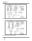
WIRING
Refer to Figures 9A and 9B
MILWAUKEE
Electric Chain Hoists, which are available for
115/230V or 230/460V, are shipped wired for 115V and 460V
respectively.Conversion of dual voltage hoists to either the
higher or lower voltage can be done simply and quickly as
follows:
1. DISCONNECT HOIST FROM POWER SUPPLY and
remove the electrical cover.
2. Each dual-voltage hoist has a terminal block assembly for
the interconnection of the electrical components of the hoist.
To convert voltage, reconnect the leads to the terminal
blocks according to the wiring diagram located inside the
electrical cover and also in Figures 9A & 9B. DO NOT move
any wires or make any changes to the electrical circuit
except at the terminal block assembly. Tug on wires to
ensure they are securely connected.
3. After converting voltage, recheck phasing and limit switch
operation (See INSTALLATION 2-c & 4, page 5).
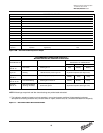
IMPORTANT: Always refer to the wiring diagram located on
the inside of the electrical cover or Figures 9A and 9B when
performing electrical repairs. Make sure all connections are
secure and check for damaged insulation.It is also imperative
that the power circuit has conductors of adequate size (See
Table 3).
LUBRICATION
Refer to Figure 11.
Proper lubrication is necessary for a long and relatively trouble-
free hoist operation. Refer to the following and the
RECOMMENDED LUBRICATION SCHEDULE for lubrication
points, type of lubricant, and frequency of lubrication.
Load Chain
Clean the load chain with acid-free solvent and coat with
SAE 90 gear oil.Wipe excess oil to prevent dripping. Never
apply grease to the chain.
Gearing
The gear case of this hoist is filled at assembly with
approximately 1½ pints of SAE 90 EP gear oil. Check oil level
by removing the oil level check plug from the side of the hoist.
With the hoist hanging level, gear oil should be even with the
hole. Change oil periodically depending on the severity of the
application and the environmental conditions (at least every
200 hours of run time).
Bearings
All bearings except hook and idler sheave bearings are
lubricated at the factory and should not require additional
lubrication. Noisy or worn bearings should be replaced.
Milwaukee Electric Tool Corporation
13135 West Lisbon Road
Brookfield, Wisconsin 53005
TEL: (800) 729-3878
Be sure the bottom of the armature does not bear
against the splined adapter “H”. As adjustments are
made, the built-in clearance will be reduced. When
this clearance is gone REPLACE BRAKE DISCS.
Minimum allowable disc thickness is .162". See
Figure 15 for further illustration.
Gap
F
G
X
B
E
A
X
D
H
C
Figure 6 — Brake Assembly