Milwaukee Electric Tool Corporation
13135 West Lisbon Road
Brookfield, Wisconsin 53005
TEL: (800) 729-3878
2. Before operating the hoist, be sure to observe the following:
a. ALWAYS DISCONNECT HOIST FROM POWER SUPPLY
before removing the electrical cover or when making any
electrical connection in the hoist or pushbutton station.
b. The ground wire (green colored) of the power cable
should always be connected to a suitable ground by
means of a screw or clamp.An alligator clip does not
make a safe ground connection.
c. When installing a three-phase hoist, make only temporary
connections at the power source. Push the “UP” button
and observe the direction of the load block. If it raises, the
phasing is correct and permanent connections may be
made at the power source. If the load block lowers when
the “UP” button is pushed, release the button immediately
since the limit switches will not operate to protect the hoist
from over-travel. Reverse any two wires (except the green
ground wire) at the power source to correct the load hook
direction (phasing). Do not change connections in the
hoist or pushbutton assembly.
d. Make sure load chain is not twisted as it travels into the
hoist.
e. Operate hoist in a hanging position only. Hoist should be
permitted to align itself for a straight line pull. Do not
attempt to pull around corners.
f. Read ASME-B30.16 Safety Code for Hoists.
3. If necessary, lubricate the chain, see LUBRICATION,
page 9.
4. Check the function of the limit switches. Before placing hoist
in operation, check limit switch adjustment. Operate
pushbutton until near stop point and inch into stop limit both
top and bottom. If either switch is not correct, adjust
according to LIMIT SWITCH ADJUSTMENT, page 8.
INSTALLATION OF CHAIN CONTAINER
ASSEMBLY (OPTIONAL ACCESSARY)
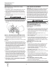
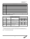
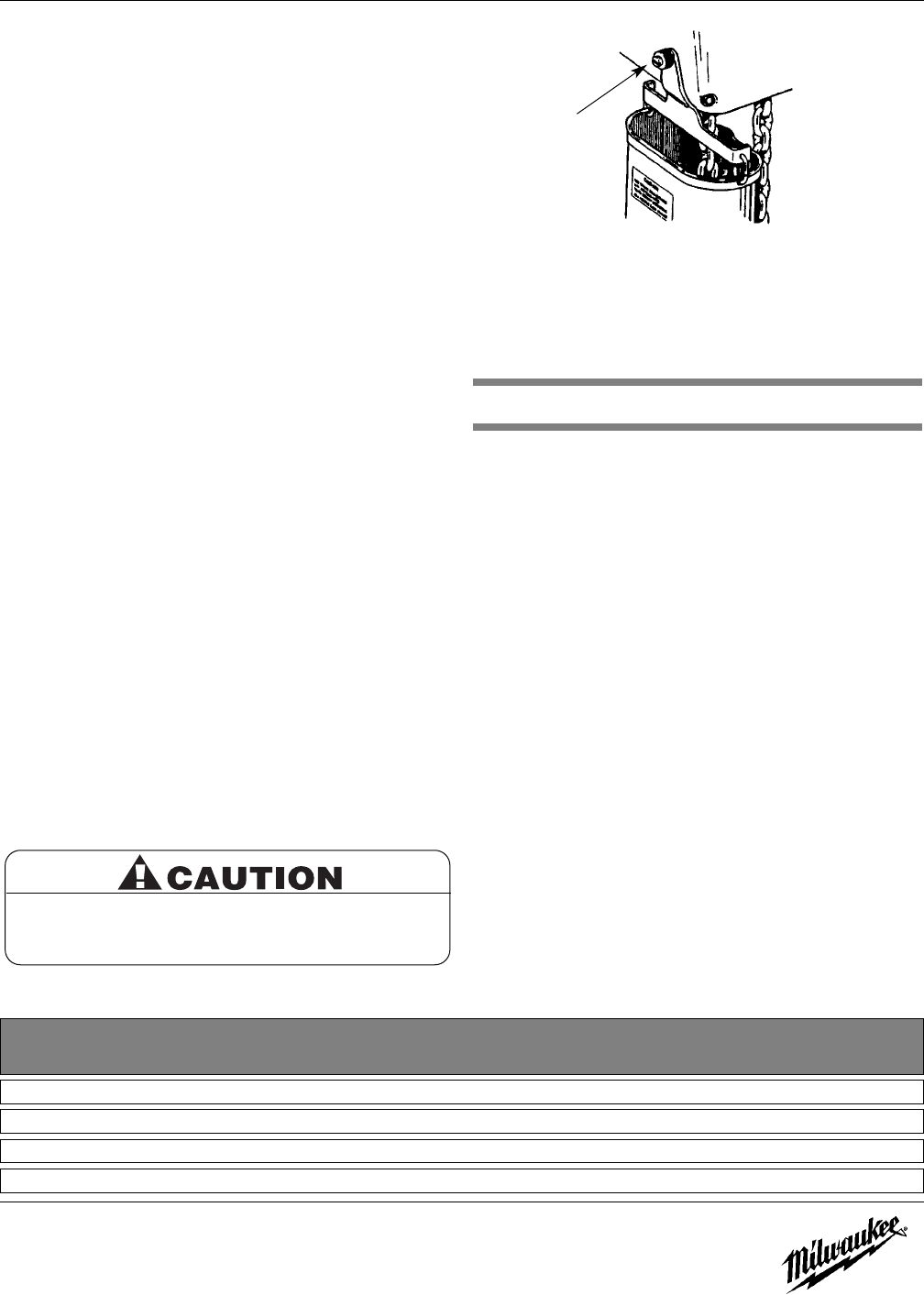
Refer to Figure 1 and Table 2.
1. Remove dead end screw and washers and let chain hang free.
2. Place chain container bracket flush against housing.
Replace washers and screw.Tighten securely.
3. Attach chain container to bracket with two open links and
then close the links.
4. Run the load hook down to its lowest position.Place the slack
end of the chain in the chain container.Feed the remainder of
the chain into the container by operating the hoist in the “UP”
direction to the top limit.This will permit the chain to pile
freely and eliminate the possibility of fouling which may occur
if the chain is placed in the container by hand.
OPERATION
This hoist is designed for safe operation within the limits of its
rated capacity. It is controlled with the “UP” and “DOWN”
buttons of the pushbutton station.There are many safety
features to protect the operator from injury due to failure of the
hoist. Here are some points which should be observed to
maintain safe operation.
1. Do not overload the hoist.
2. Do not make extreme side pulls with the hoist.
3. Operate the hoist only in a hanging position with
adequate support.
4. Do not “sling” the load hook and chain around the load.
Use an approved sling.
5. Be sure there are no twists in the load chain as it travels into
the hoist housing.This condition should be constantly
checked on double chain hoists because it is possible for the
load block to be “capsized” or turned over one or more times.
6. Before raising a load, always check to see that it is held
securely in the hook or sling chains, etc. Raise the load
only until the load chain is taut and then double check the
rigging before continuing to raise the load.
7. Do not stand beneath a load! Do not move a load in such a
manner as to endanger personnel.
8. Do not lower into areas where visibility is obscured unless
someone else is guiding the operation.
9. Use common sense at all times when operating a hoist.
10. Do not operate if direction of hook travel is not the same as
indicated on button being pushed.
5
Do not allow load to come in contact with chain
container. If this situation exists reset the “UP” limit
switch (See LIMIT SWITCH ADJUSTMENT, page 8) so
that hook block stops below chain container.
Standard Shipping
Hoist Lifts Chain Container Weight Dimensions in Inches
Capacity (ft) Required (lbs) Width Length Depth
Table 2 - Optional Chain Container
1/2 & 1 Ton 10, 15, & 20 48-12-0111 3 3 6½ 11½
2 Ton 10 48-12-0111 3 3 6½ 11½
2 Ton 15 48-12-0112 4 3 6½ 18½
2 Ton 20 48-12-0113 5 6 6½ 27
Figure 1 — Installing Chain Container Assembly
Dead-end Screw


