


© National Instruments Corporation 5 SCXI-1125 Calibration Procedure
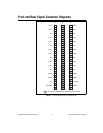
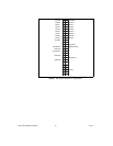
7. Connect the calibrator to the appropriate analog input, starting
with channel 0. Refer to Figure 1 to determine which pins on the
96-pin front connector correspond to the positive and negative inputs
of the specified channel. For example, the positive input for channel 0
(CH0+) is pin A32. The negative input for channel 0 (CH0–)ispin
C32. If you are using an SCXI-1320 terminal block connected to the
SCXI-1125, connect the calibrator to the CH0+ and CH0– inputs.
8. Call
SCXI_Single_Chan_Setup
to configure the module for
single-channel measurements. Set the following parameters:
• SCXIchassisID—The value assigned by MAX
• moduleSlot—1
• moduleChan—The same channel number from step 7
• DAQdeviceNumber—The device number assigned by MAX for
the E Series DAQ device
9. Call
SCXI_Set_Gain
to set the gain you want to test on the module.
Set the following parameters:
• SCXIchassisID—The IDobtained whenthe chassis is configured
with MAX
• moduleSlot—1
• channel—The channel number from step 7
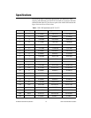
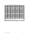
• gain—The first gain value you want to test—you can find this
gain value in Table 1.
10. Call
SCXI_Configure_Filter
to configure the filter setting on the
module. Set the following parameters:
• SCXIchassisID—The IDobtained whenthe chassis is configured
with MAX
• moduleSlot—1
• channel—The channel number from step 7
• filterMode—1
• cutoffFrequency—10,000
11. Set the calibrator to output the test point voltage from Table 1.
12. Call
DAQ_Op
. Set the following parameters:
• deviceNumber—ThedevicenumberoftheDAQdevice
• channel—0
• gain—1 for 16-bit E Series devices or –1 for 12-bit E Series
devices
• count—5,000
• sampleRate—10,000