


NOTE: Incorrect cable connections may result in irregular
operation, damage display quality/components of LCD module,
and/or shorten the module’s life.
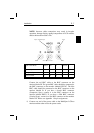
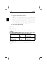
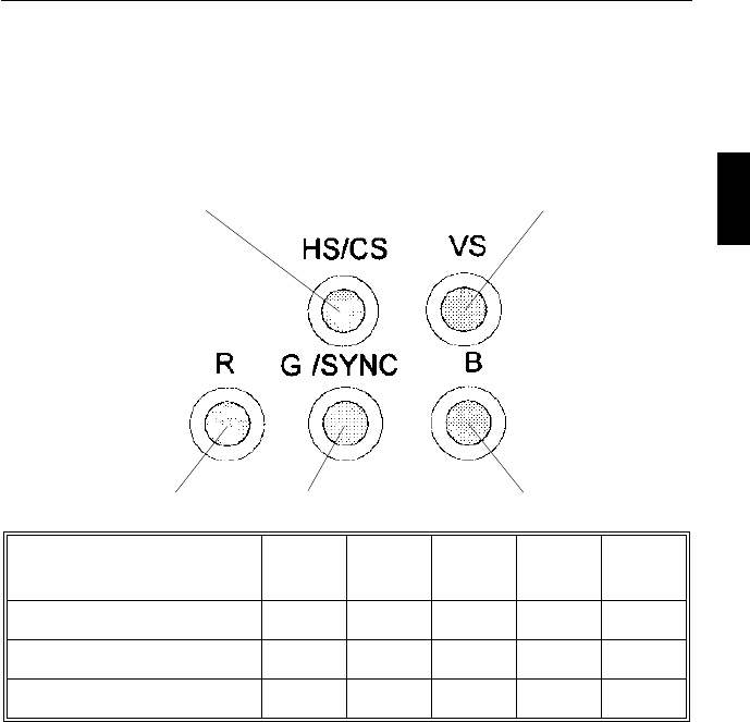
Input Video Mode HS/CS VS R G/SYNC B
Separate Sync OOOOO
Composite Sync OXOOO
Sync on Green XXOOO
0 – BNC connector is utilized; X - BNC connector is not utilized
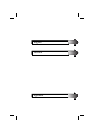
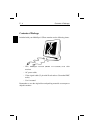
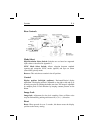
Connect the red BNC cable to the BNC connector on the
monitor labeled R. The green BNC cable should be connected to
the BNC connector on the monitor labeled G/SYNC. The blue
BNC cable should be connected to the BNC connector on the
monitor labeled B. If you have a fourth BNC connector
(Composite Sync), connect it to the BNC connector on the
monitor labeled HS/CS. If you have a fifth BNC connector
(Vertical Sync), connect it to the BNC connector on the monitor
labeled VS. Please see Appendix 1 for pin assignments.
8. Connect one end of the power cable to the MultiSync LCD
300
monitor and the other end to the power outlet.
V SyncH Sync / Composite Sync
Red BlueGreen / Sync onGreen
Installation E - 7