


English-10
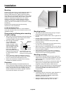
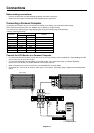
Attaching Mounting Accessories
The display is designed for use with the VESA mounting
system.
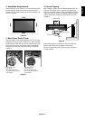
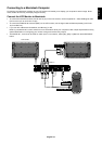
1. Attach Mounting Accessories
Mounting accessories can be attached while the monitor
is on the Tabletop Stand in the upright position (Figure 1).
Be careful to avoid tipping monitor when attaching
accessories. After accessories are attached, stand can
be removed (Figure 3).
Mounting accessories can be attached with the monitor in
the face down position. To avoid damaging the screen face,
place the protective sheet on the table underneath the LCD.
The protective sheet was wrapped around the LCD in the
original packaging. Make sure there is nothing on the table
that can damage the monitor.
When using mounting accessories other than NEC
compliant and approved, they must comply with the VESA-
compatible mounting method. NEC strongly recommends
using screws M6 size and 10mm in length. If using screws
longer than 10mm, check the depth of the hole.
(Recommended Fasten Force: 470-635N•cm)
NEC recommends using mounting interface that comply with
UL1678 standard in North America.
This device cannot be used or installed without the Tabletop
Stand or other mounting accessory for support. For proper
installation it is strongly recommended to use a trained,
NEC authorized service person. Failure to follow NEC
standard mounting procedures could result in damage to the
equipment or injury to the user or installer. Product warranty
does not cover damage caused by improper installation.
Failure to follow these recommendations could result in
voiding the warranty.
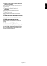
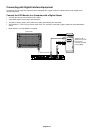
2. Stand Removal
To detach stand, place the monitor face down as shown in
Figure 2. Remove the screws from the back of the stand as
indicated in Figure 3. Remove the 2 additional screws
located at the bottom of the stand (Figure 4). Lift up stand to
remove after stand is removed, replace the screws into the
original holes.
Figure 1
VESA Mounting Interface
Tabletop Stand
Protective Sheet
Tabletop StandTable
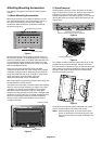
Figure 2
Circles indicate screw locations (8 screws)
Figure 3
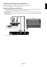
To re-attach the stand. Place the monitor face down on the
protective sheet to prevent damage. Remove the screws
from their holes as indicated in Figure 3. Slide the stand into
place, making sure that the inside tabs located on the left
and right of the stand are placed into the corresponding
slots on the display (Figure 5).
Figure 5
The bottom of the stand should fit underneath the monitor.
Use the screws to secure the stand to the monitor.
NOTE: When removing stand, be sure to remove the 2
screws on the bottom of the stand (Figure 4). Not
removing these screws will result in damage to the
monitor.
Figure 4
2 screws under stand