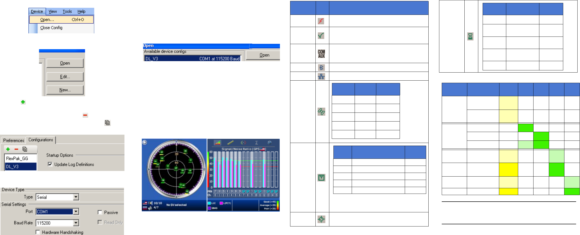
2. Select Open.... from the Device menu.
3. Select the New... button in the Open dialog box. The Options
| Configuration dialog opens.
4. Use the button at the top of the configurations selection
box to add a new configuration. To delete a configuration,
select it from the list and click on the button. To
duplicate an existing configuration, click on the button.
You can select any name in the list and edit it to change it.
5. Select Serial from the Type list and select the PC/laptop
port, that the DL-V3 is connected to, from the Port list.
6. Select 115200 from the Baud Rate list.
7. Uncheck the Use hardware handshaking checkbox.
8. Select OK to save the new device settings.
9. Select the new configuration from the Available device
configs area of the Open dialog.
10. Select the Open button to open DL-V3 communications.
As CDU establishes the communication session with the
receiver, a progress box is displayed.
USING CDU
CDU provides access to key information about your receiver and
its position. The information is displayed in windows accessed
from the View menu. For example, select Position Window from
the View menu to display the position solution of the receiver. To
show details of the GNSS and geostationary (SBAS) satellites
being tracked, select a Tracking Status Window (GPS or
GLONASS) from the View menu. Select Help from the main
menu for more details on CDU, its windows and features.
DL-V3 LEDS
The LEDs on the front of the DL-V3 represent these categories:
LED
Name
LED
Icon
Indicators
Power
Orange: receiver is powered
Green: receiver is turned on
Receiver
Status
Orange flash: at start-up
Off: normal operation
Orange flash again: status event
COM1/
COM2/
AUX
Green flash (top): transmitting
Amber flash (bottom): receiving
COM3
Blue flashing: Bluetooth active
COM3
Orange glow: Ethernet active
Satellite
Tracking
Flash Card
Memory
Positioning
Mode
See Table 1 starting on the next panel
Continued on the next panel
LED#
# of
SVs
LED
Color
1 (left) ≤ 3 Red
2 4 or 5 Amber
3 6 or 7 Green
4 8 or 9 Green
5 (right) ≥ 10 Green
# of
LEDs
Capacity
LED
Color
1 Capacity ≤ 20%
Red
a
a.This red LED can also mean that the card was
not formatted, and placed in the receiver,
when the receiver was powered off.
240% ≥ Capacity > 20%
Amber
360% ≥ Capacity > 40%
Green
480% ≥ Capacity > 60%
Green
5 Capacity > 80%
Green
Occupation
Time
LED#
Baseline
Length (km)
LED
Color
1 (left)
≤ 5
Green
2
> 5
≤ 10
Green
3
> 10
≤ 15
Green
4
> 15
≤ 20
Green
5 (right)
≥ 20
Green
Table 1: Positioning Mode LEDs
1
Position
Mode
Position
Mode Detail
1
left
2 3 4
5
right
Single
Point
Autonomous
(fixed height)
Amber Off Off Off Off
Autonomous
(3D)
Amber Off Off Off Off
Differential
GPS
SBAS
Off
Green Off Off Off
CDGPS
Off Off
Green Off Off
DGPS
Off Green Green Off Off
RTK (see
note below)
Float (RT-20
unconverged)
Amber Off Off Green Off
RTK (see
note below)
Float (RT-20)
Amber Off Off Green Off
RTK
Fixed (RT-2,
unconverged)
Amber Off Off Off Green
RTK Fixed (RT-2)
Amber Off Off Off Green
Continued on the next page
The LEDs show the total number of satellites used in the solution (GPS or
GPS+GLONASS) without making a distinction between GPS and
GLONASS. Check the Constellation window in CDU for details on the
availability of GPS and GLONASS satellites.
1 Table Cell Color: Solid: LED glowing; Dim: LED flashing; White: Off


