


Enabling Real-Time Kinematic (RTK) Positioning
Corrections can be transmitted from a base station to a rover
station to improve position accuracy. The base station is the
GNSS receiver that acts as the stationary reference. It has a
known position and transmits correction messages to the rover
station. The rover station is the GNSS receiver that does not
know its exact position and can receive correction messages
from a base station to calculate differential GNSS positions.
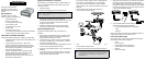
You must create a data link between the base station and rover
station (two NovAtel receivers) to transfer corrections. SBAS
and L-band corrections can be accomplished with one receiver
and are exceptions to the base/rover concept. A link capable of
at least 9600 bits per second and less than 4.0 seconds of
latency is recommended. When connecting a base station to a
SPAN-SE, the data link must connect to the SPAN-SE OEMV3
COM port, found on the I/O 1 Green Cable.
When the base and rover stations are set up, you can configure
them for RTCA, RTCM, RTCMV3, CMR+ or CMR corrections.
Below is an RTCM example. Replace the latitude, longitude and
height coordinates shown with those of your base:
Base
interfacemode com2 none rtcm off
fix position 51.11358042 -114.04358013 1059.4105
log com2 rtcm3 ontime 10
log com2 rtcm22 ontime 10 1
log com2 rtcm1819 ontime 1
log com2 rtcm1 ontime 5
log com2 rtcm31 ontime 5,1
(optional GLONASS PSRDIFF)
log com2 rtcm32 ontime 10,2
Rover
gnsscardconfig rtcm none off
RT-2 and RT-20-capable SPAN-SE receivers with AdVance RTK
are real-time kinematic products developed by NovAtel. Optimal
RTK performance requires both the base and rovers be NovAtel
products. However, AdVance RTK operates with equipment from
other manufacturers when using RTCM messaging.
RT-2 and RT-20 are supported by GPS+GLONASS and GPS-
only OEMV-based models. Also, RT-20 with GPS+GLONASS
provides faster convergence.
CONFIGURING THE SPAN IMU
Configure SPAN with Connect
Follow these steps to enable INS as part of the SPAN system
using the NovAtel Connect software utility:
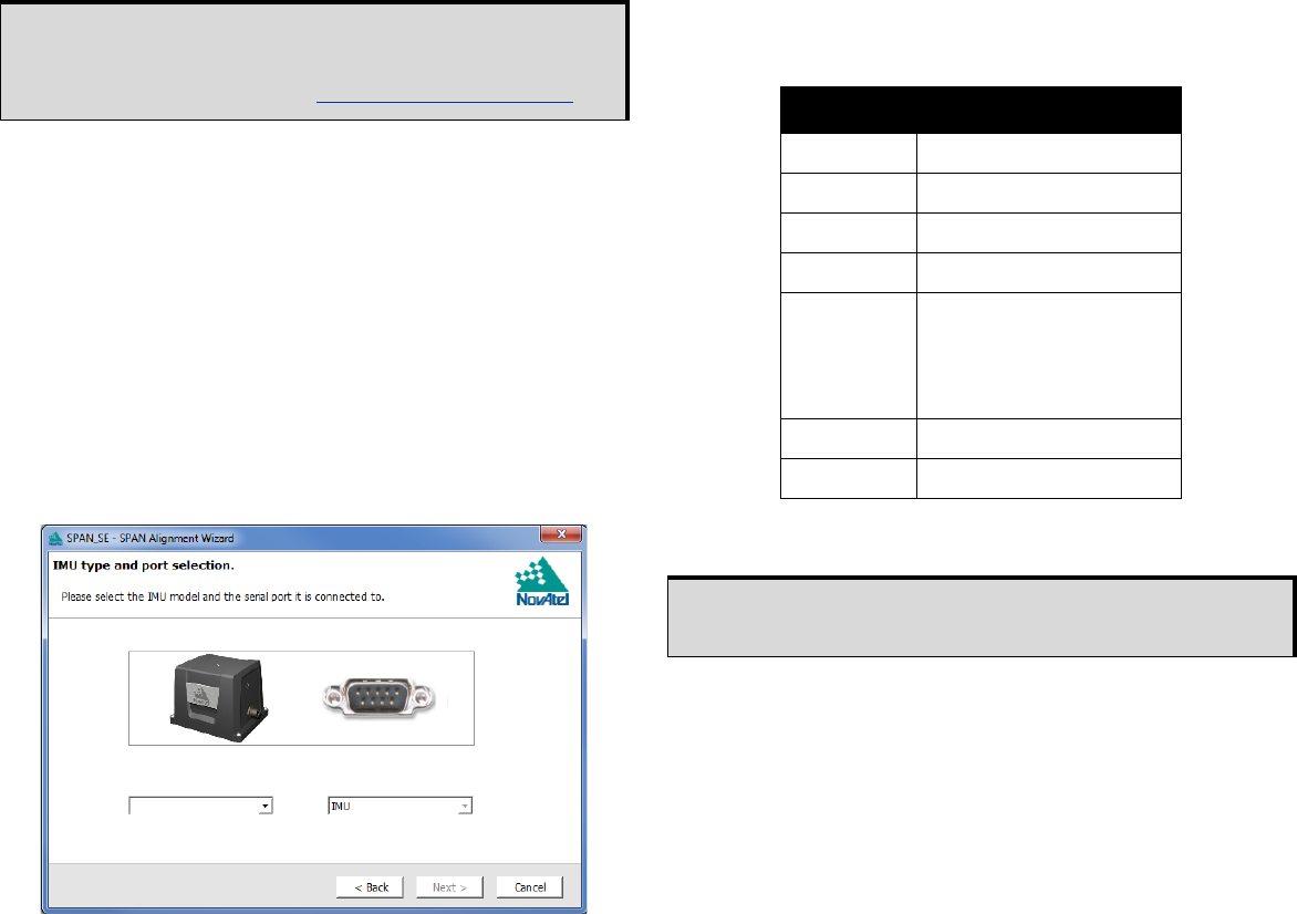
1. Select Wizards | SPAN Alignment from the Connect toolbar.
This wizard takes you through the steps to complete a
coarse or fast alignment, select the type of IMU and
configure the receiver to IMU port to accept IMU data.
When you have made your selections in the SPAN wizard, click
the OK button to enable the SPAN system. When the system is
enabled, raw IMU data becomes available and the INS filter
starts.
Configure SPAN Manually
Follow these steps to enable INS as part of the SPAN system
using software commands:
1. Issue the SETIMUTYPE command to specify the IMU.
The inertial filter starts when the GNSS solution is solved and
the IMU is connected.
2. Use the SETIMUTOANTOFFSET command to set the
distance from the IMU to the GNSS antenna. The offset
between the antenna phase centre and the IMU axes must
remain constant and be accurate (m). The X (pitch), Y (roll)
and Z (azimuth) directions are clearly marked on the IMU
enclosure. The SETIMUTOANTOFFSET parameters are
(where the standard deviation fields are optional):
x_offset y_offset z_offset [x_stdev] [y_stdev] [z_stdev]
A typical RTK GNSS solution is accurate to within a few
centimeters. For the integrated INS/GNSS system to have
this level of accuracy, the offset must be measured to within
a millimetre. Any bias between the two systems appears in
the output position. For example, a 10 cm error in recording
this offset will result in at least a 10 cm error in the output.
If you cannot measure the IMU to GNSS antenna offset
precisely, perform the lever arm calibration routine to
estimate offset. Refer to the SPAN-SE User Manual for
details.
Configuration for Alignment
A coarse alignment routine requires the vehicle to remain
stationary for at least 1 minute. If that is not possible, an
alternate fast alignment routine is available. The fast or moving
alignment is performed by estimating the attitude from the GPS
velocity vector and injecting it into the SPAN filter as the initial
system attitude.
A static coarse alignment is not available for the IMU-CPT or
IMU-HG1930 IMUs. The fast, or kinematic alignment must be
used instead. A stationary alignment is only possible with a dual
antenna SPAN-SE-D, or if the SETINITAZIMUTH or
SETINITATTITUDE commands are issued. See the SPAN-SE
User Manual for more information.
If your have a dual antenna system (SPAN-SE-D), the default
alignment mode is a dual antenna alignment. Once you enter
the primary and secondary antenna offsets (with
SETIMUTOANTOFFSET and SETIMUTOANTOFFSET2
respectively) the system will automatically align as soon as it
computes a dual antenna solution. See the SPAN-SE User
Manual for more information.
1.Refer to the GPGST log’s usage box in the OEMV Firmware
Reference Manual for a definition of RMS and other statistics.
2.For more base/rover configurations, search for “rover base” on
our Knowledge Database at: http://support.novatel.com/home.
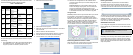
Table 2: Enable INS Commands
IMU Type SETIMUTYPE
LN-200 IMU_LN200
iIMU-FSAS IMU_IMAR_FSAS
IMU-CPT IMU_KVH_COTS
UIMU-LCI IMU_LITEF_LCI
IMU-HG1700
IMU_HG1700_AG11, or
IMU_HG1700_AG17, or
IMU_HG1700_AG58, or
IMU_HG1700_AG62
IMU-HG1900 IMU_HG1900_CA29
IMU-HG1930 IMU_HG1930_AA99
A GNSS antenna must be connected and actively tracking satellites
for correct operation.