


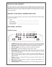
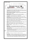
10. Power LED - when illuminated (green) indicates that the amplifier is on.
Protect LED - when illuminated (red) indicates that the amplifier protective cir-
cuitry has been activated due to thermal, output short, supply undervoltage or
supply overvoltage.
ESP
®
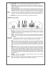
Indicator LED - when illuminated (yellow) indicates ESP
®
functionality and
is used by the ESP
®
computer to communicate amplifier operational modes. The
LED flash characteristics will assists in diagnosing the type of fault (see Appendix).
NOTE: The LED on top of the amplifier may also illuminate and flash with the ESP
®
LED
indicator, if this option has been enabled by your installer (requires Bitwriter
®
).
12. ESP
®
Port - connection port for Bitwriter
®
or ESP2 security system.
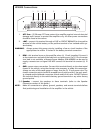
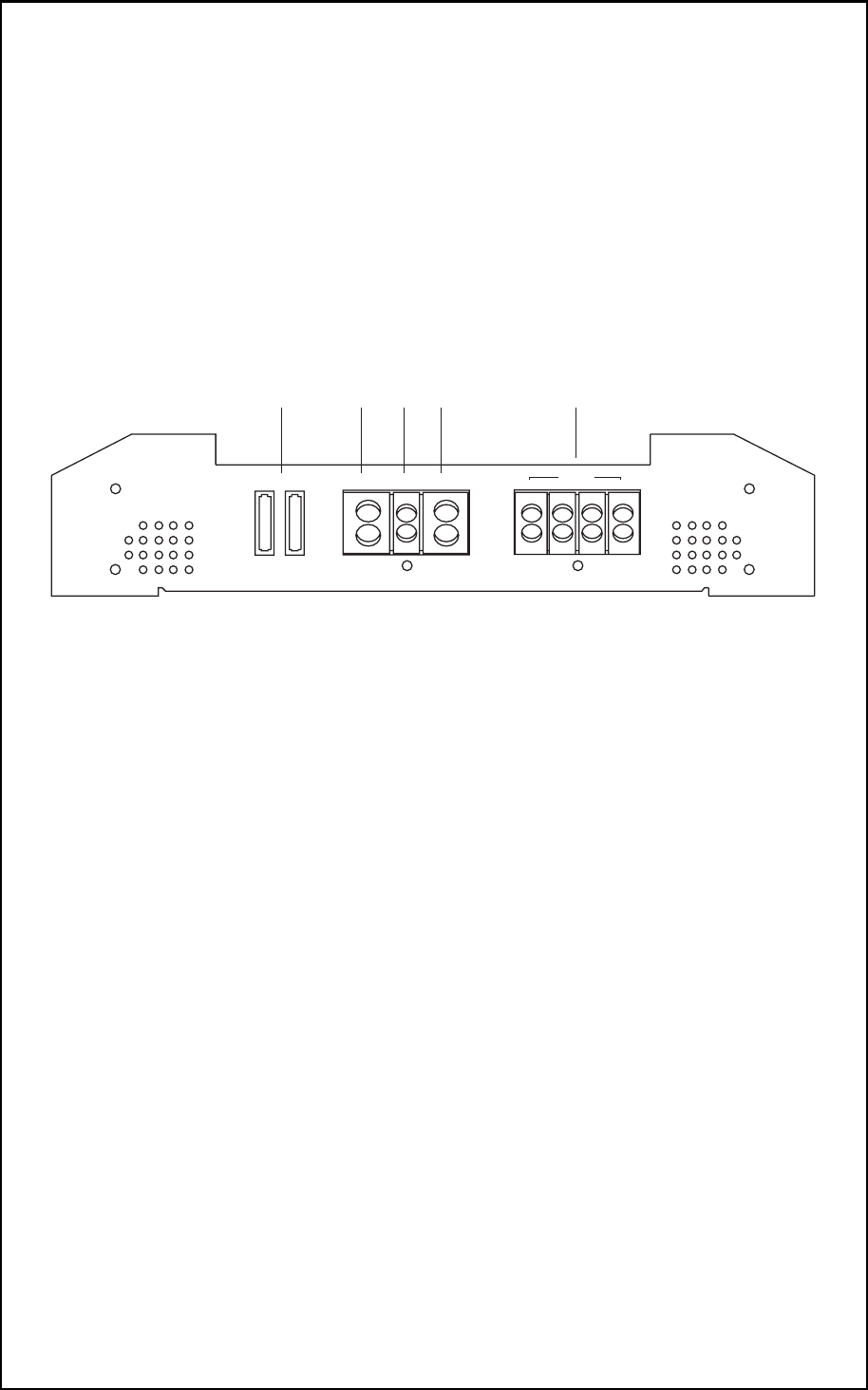
HP2800 Connections
1. ATC Fuse - (2) 30-amp ATC fuses protect the amplifier against internal electrical
damage and is meant to protect the amplifier only. All other power connections
should be fused at the source.
2. +BAT - connect this terminal through a FUSE or CIRCUIT BREAKER to the positive
terminal of the vehicle battery or the positive terminal of an isolated audio sys-
tem battery.
WARNING: Always protect this power wire by installing a fuse or circuit breaker of the
appropriate size within 12 inches of the battery terminal connection.
3. REM - this terminal turns on the amplifier when (+) 12 volt is applied. Connect it
to the remote turn on lead of the head unit or signal source. If a (+) 12 volt remote
turn lead is not available, a Remote Power Adapter (P/N #55000) can be used to
supply a remote turn on signal. DO NOT connect this terminal to constant (+) 12
volt.
4. GND - power return connection. Connect this terminal directly to the sheet metal
chassis of the vehicle, using the shortest wire necessary to make this connection.
Always use wire of the same gauge or larger than the (+) 12 volt power wire. The
chassis connection point should be scraped free of paint and dirt. Use only quali-
ty crimped and/or soldered connectors at both ends of this wire. DO NOT connect
this terminal directly to the vehicle battery ground terminal or any other factory
ground points.
5. Speaker - connect the speakers to these terminals. (refer to the Speaker
Connection section of this guide.)
NOTE: Make all connections to power, ground, speakers, and remote terminals before
final positioning and installation of the amplifier in the vehicle.
SPEAKER
+BAT REM GND
FUSE
1234 5
+
L CH
+
R CH
-
L CH
-
R CH
BRIDGE
4
© 2005 Directed Electronics, all rights reserved