


5
© 2005 Directed Electronics, all rights reserved
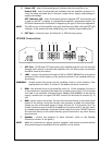
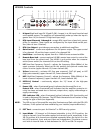
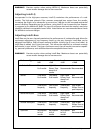
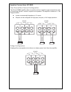
HP4800 Controls
1. Hi Input (high level input Ch 1/2 and Ch 3/4) - Accepts 1v to 10v input from the head
unit’s speaker output. The amplifier will automatically wake-up when the input is
greater than 1V (on channel 1/2 high level input only).
2. RCA Input Channels 1 through 4 - accepts RCA input from a head unit, pream-
plifier, or equalizer. These inputs are configured by the Input Mode switch posi-
tion (refer to item 13 below).
3. RCA Line Output - provides easy connection to additional amplifiers.
4. Gain Control - continuous adjustment for full power output. The upper control
is for channels 1/2 and the lower control is for channels 3/4.
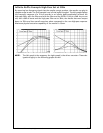
5. Intelli-Bass - continuously adjusts from 0 to 12dB of boost centered at 45Hz.
6. Remote Bass Jack - connects optional HP-RB1 remote bass control to control the
bass level from the driver’s seat. The HP-RB1 is only active when the crossover
switch (lower switch) for channels 3/4 is at the LPF setting.
7. LPF (Low-Pass Frequency Control) - adjusts the frequency (50Hz–500Hz) of the
upper crossover frequency. When set for this position the optional remote bass
control is active (upper channels 1/2, lower channels 3/4).
8. X-Over (cross-over) - activates LPF (low pass crossover), FLAT (all pass), or HPF
(high pass crossover) (upper channels 1/2, lower channels 3/4).
9. HPF (High-Pass Frequency Control) - adjusts the frequency (50Hz–500Hz) of the
lower crossover frequency (upper channels 1/2, lower channels 3/4).
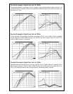
10. INTELLI-Q Control - continuously adjusts the "Q" boost of the high-pass
crossover.
11. Power LED - when illuminated (green) indicates that the amplifier is on.
Protect LED - when illuminated (red) indicates that the amplifier protective cir-
cuitry has been activated due to thermal, output short, supply undervoltage or
supply overvoltage.
ESP
®
Indicator LED - when illuminated (yellow) indicates ESP
®
functionality and
is used to diagnose ESP
®
features. The LED flash characteristics will assists in diag-
nosing the type of fault (see Appendix).
NOTE: The LED on top of the amplifier may also illuminate and flash with the ESP
®
LED
indicator, if this option has been enabled by your installer (requires Bitwriter
®
).
12. ESP
®
Port - connection port for Bitwriter
®
or ESP2 security system.
13. Input Mode - 1/2 channel or 3/4 channel selectable. In the 1/2 CH position, the
input to channels 1 and 2 are also supplied to channels 3 and 4, respectively. In the
3/4 CH position all 4 channels are supplied separately When the switch is to the
left (4 CH position), front and rear inputs are independent. This allows a source
unit with an internal fader to fade between the 1/2 CH and 3/4 CH outputs.
GAIN
MIN MAX
INTELLIBASS
0dB 12dB
GAIN
MIN MAX
2 CH
1 CH
INPUT
4 CH
3 CH
R CH
L CH
LINE OUT
REMOTE
LPF FLAT HPF
X-OVER
INTELLI-Q
MIN MAX
HPF
50Hz 500Hz
LPF
50Hz 500Hz
LPF FLAT HPF
X-OVER
HPF
50Hz 500Hz
LPF
50Hz 500Hz
POWER
(GREEN)
PROTECT
(RED)
ESP
INDICATOR
(YELLOW)
ESP PORT
123456 789101112 13
HI INPUT
1/2 CH
HI INPUT
3/4 CH
INPUT
MODE
1/2 CH
3/4 CH