


12 13
CQ-C1110W/C1100WCQ-C1110W/C1100W
9
E
N
G
L
I
S
H
10
E
N
G
L
I
S
H
M
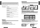
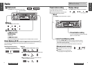
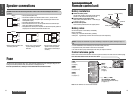
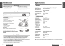
Anti-Theft system
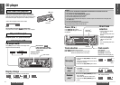
fInstall the removable face
plate
q Slide the left side of the removable face plate in
place.
w Press the right end of the removable face plate
until “click” is heard.
Caution:
• This face plate is not waterproof. Do not expose it to water or excessive moisture.
• Do not remove the face plate while driving your car.
• Do not place the face plate on the dashboard or nearby areas where the temperature rises to high level.
• Do not touch the contacts on the face plate or the main unit, since this may result in poor electrical con-
tacts.
• If dirt or other foreign substances get on the contacts, wipe them off with a clean and dry cloth.
This unit is equipped with a removable face plate. Removing this face plate makes the radio totally inoperable.
Place the removable
face plate into case
q Gently press the bottom of the case and
open the cover. Place the face plate into
the case and take it with you when you
leave the car.
w
q
Removable face plate case
Tab
Cutout
Remove the removable
face plate
Switch off the power of the unit.
qPress []. The remov-
able face plate will be
opened.
w Push the face plate to
either the right or left.
e Pull it out toward you.
q Press
q
w
Contact
w
Release button
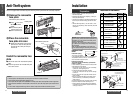
Q’tyItemNo. Diagram
Installation hardware
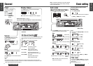
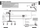
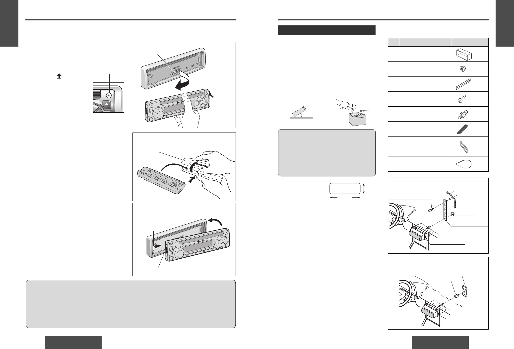
Installation
• Before installation, check the radio operation with
antenna and speakers.
• Disconnect the cable from the negative (–) battery ter-
minal (see caution below).
• Unit should be installed in a horizontal position with the
front end up at a convenient angle, but not more than
30°.
• Remove Mounting Collar q and Trim Plate u from
the main unit temporarily, which are already mounted
at shipment*.
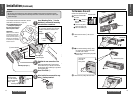
Dashboard instal-
lation
Installation opening
The unit can be installed
in any dashboard having an opening as shown at right.
The dashboard should be 4.5 mm - 6 mm thick in
order to be able to support the unit.
Installation precautions
This product should be installed by a professional
installer, if possible.
In case of difficulty, please consult your nearest autho-
rized Panasonic Service Center.
1.This system is to be used only in a 12 V, DC battery
system (car) with negative ground.
2.Follow the electrical connections carefully
(➡ page 16). Failure to do so may result in damage
to the unit.
3.Connect the power lead (red) after all other connec-
tions are made.
4.Be sure to connect the battery lead (yellow) to the
positive terminal (+) of the battery or fuse block
(BAT) terminal.
5.Insulate all exposed wires to prevent short circuiting.
6.Secure all loose wires after installing the unit.
7.Please carefully read the operating and installation
instructions of the respective equipment before con-
necting it to this unit.
Preparation
30˚ or less
Caution: Various settings that have been stored
in the memory in other on-board equipment (car
navigation etc.) may be lost if the battery termi-
nals are disconnected.
Therefore, we recommend to make a record of
or to back up the settings before disconnecting
the terminals.
After completing installation of the main unit,
set the equipment again according to the record.
182 mm
53 m
m
Fire Wall of Car
w Hex. Nut
e Rear Support Strap
t Mounting Bolt
q Mounting Collar
r Tapping Screw
3 mmø
(a) Using the Rear Support Strap
Rubber Cushion
(Option)
t Mounting Bolt
q Mounting Collar
Rear Support Bracket
(Provided on the car)
(b) Using the Rubber Cushion (option)
q
1
1
1
1
1
1
1
2
Mounting Collar*
(FX0214C316ZA)
Hex. Nut (5 mmø)
(YJN994C002ZA)
Rear Support Strap
(YFG044C002ZA)
Tapping Screw (5 mmø×16 mm)
(XTT5+16AFK)
Mounting Bolt (5 mmø)
(YEJV014C002A)
Power Connector
(YEAJ02877)
Trim Plate*
C1110W: (YFC054C058ZA)
C1100W: (YFC054C057ZA)
Dismounting Plate
(YFX214C323ZA)
w
e
r
t
y
u
i