


E
N
G
L
I
S
H
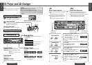
CQ-DF501/DF301W
21
E
N
G
L
I
S
H
11
CQ-DF501/DF301W
20
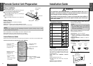
Installation Guide (Continued)
E
N
G
L
I
S
H
12
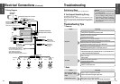
Speakers
Connect the speaker wires. See the wiring diagram
(➡ pages 25, 26) for the proper hookups. Follow
the diagram carefully to avoid damaging the speak-
ers and the stereo unit.
The speakers used must be able to handle more
than 45 W of audio power. If using an optional
audio amplifier, the speakers should be able to han-
dle the maximum amplifier output power. Speakers
with low input ratings can be damaged. Speaker
impedance should measure 4–8 ≠, which is typi-
cally marked on most speakers. Lower or higher
impedance speakers will affect output and can
cause both speaker and stereo unit damage.
Motor Antenna
Connect the car motor antenna lead to the dark
blue motor antenna relay control lead.
Battery
Connect the yellow battery lead to the correct radio
wire or to the battery fuse port on the fuse block.
Antenna
Connect the antenna by plugging the antenna lead
into the antenna receptacle.
Equipment
Connect any optional equipment such as an ampli-
fier, according to the instructions furnished with
the equipment. Leave about 30 cm of distance be-
tween the speaker leads/amplifier unit and the an-
tenna/antenna extension cord. Read the operating
and installation instructions of any equipment you
will connect to this unit.
Power
Connect the red power lead to the correct car radio
wire or to the appropriate fuse port on the fuse
block.
If the stereo unit functions properly with all these
connections made, disconnect the wires and pro-
ceed to the final installation.
❐ Final Installation
❐ Final Checks
Lead Connections
Connect all wires, making sure that each connec-
tion is insulated and secure. Bundle all loose wires
and fasten them with tape so they will not fall down
later. Now insert the stereo unit into the mounting
collar.
Congratulations! After making a few final checks,
you’re ready to enjoy your new auto stereo system.
1. Make sure that all wires are properly connected
and insulated.
2. Make sure that the stereo unit is securely held in
the mounting collar.
3. Turn on the ignition to check the unit for proper
operation.
If you have difficulties, consult your nearest author-
ized professional installer for assistance.
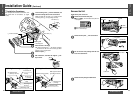
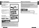
❐ Preparation
≥We strongly recommend that you wear gloves
for installation work to protect yourself from
injuries.
≥When bending the mounting tabs of the
mounting collar with a screwdriver, be careful
not to injure your hands and fingers.
≥Disconnect the cable from the negative
-
battery
terminal (see caution below).
≥Unit should be installed in a horizontal position
with the front end up at a convenient angle, but
not more than 30o.
Caution:
≥Do not disconnect the battery terminals of a
car with a trip or navigational computer since
all user settings stored in memory will be lost.
Instead take extra care with installing the unit
to prevent shorts.
Less than 30x
Dashboard Installation
Installation Opening
182 mm
53 mm
This unit can be installed in any dashboard having
an opening as shown above. The dashboard should
be 4.75 mmj5.56 mm thick in order to be able to
support the unit.
The first step in installation is to identify all the car
wires you’ll use when hooking up your sound sys-
tem.
As you identify each wire, we suggest that you label
it using masking tape and a permanent marker.
This will help avoid confusion when making con-
nections later.
Note:
≥Do not connect the power connector to the stereo
unit until you have made all connections. If there
are no plastic caps on the stereo hooking wires,
insulate all exposed leads with electrical tape until
you are ready to use them. Identify the leads in
the following order.
Power Lead
If your car has a radio or is pre-wired for one:
Cut the connector wires one at a time from the plug
(leaving the leads as long as possible) so that you
can work with individual leads.
❐ Identify All Leads
Turn the ignition on to the accessory position, and
ground one lead of the test bulb to the chassis.
Touch the other lead of the test bulb to each of the
exposed wires from the cut radio connector plug.
Touch one wire at a time until you find the outlet
that causes the test bulb to light.
Now turn the ignition off and then on. If the bulb
also turns off and on, that outlet is the car power
lead.
If your car is not wired for an audio unit:
Go to the fuse block and find the fuse port for radio
(RADIO), accessory (ACC), or ignition (IGN).
Battery Lead
If your stereo unit has a yellow lead, you will need
to locate the car’s battery lead. Otherwise you may
ignore this procedure. (The yellow battery lead pro-
vides continuous power to maintain a clock, memo-
ry storage, or other function.)
If your car has a radio or is pre-wired for one:
With the ignition and headlights off, identify the car
battery lead by grounding one lead of the test bulb
to the chassis and checking the remaining exposed
wires from the cut radio connector plug.
If your car is not wired for an audio unit:
Go to the fuse block and find the fuse port for the
battery, usually marked BAT.
Speakers
Identify the car speaker leads. There are two leads
for each speaker which are usually color coded.
A handy way to identify the speaker leads and the
speaker they are connected with is to test the leads
using a 1.5 V AA battery as follows.
Hold one lead against one pole of the battery and
stroke the other lead across the other pole. You will
hear a scraping sound in one of the speakers if you
are holding a speaker lead.
If not, keep testing different lead combinations until
you have located all the speaker leads. When you
label them, include the speaker location for each.
Antenna Motor
If your car is equipped with an automatic power an-
tenna, identify the car motor antenna lead by con-
necting one bulb tester lead to the car battery lead
and touching the remaining exposed wires from the
cut radio connector plug one at a time. You will
hear the antenna motor activate when you touch
the correct wire.
Antenna
The antenna lead is a thick, black wire with a metal
plug at the end.
❐ Connect All Leads
Now that you have identified all the wires in the car,
you are ready to begin connecting them to the
stereo unit wires. The wiring diagram (➡ pages 25,
26) shows the proper connections and color coding
of the leads.
We strongly recommend that you test the unit be-
fore making a final installation.
You can set the unit on the floor and make tempo-
rary connections to test the unit. Use electrical tape
to cover all exposed wires.
Important:
≥Connect the red power lead last, after you
have made and insulated all other connec-
tions.
Ground
Connect the black ground lead of the power con-
nector to the metal car chassis.