


15
E
N
G
L
I
S
H
16
E
N
G
L
I
S
H
2726
CQ-C1200U/C1120U/C1110U/C1100U CQ-C1200U/C1120U/C1110U/C1100U
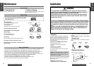
Caution: Connect the red power lead last, after
you have made and insulated all other connec-
tions.
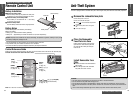
Installation (Continued)
❐ Identify All Leads
The first step in installation is to identify all the car wires
you’ll use when hooking up your sound system.
As you identify each wire, we suggest that you label it
using masking tape and a permanent marker. This will
help avoid confusion when making connections later.
Note: Do not connect the power connector to the stereo
unit until you have made all connections. If there are no
plastic caps on the stereo hooking wires, insulate all
exposed leads with electrical tape until you are ready to
use them. Identify the leads in the following order.
Power Lead
If your car has a radio or is pre-wired for one:
Cut the connector wires one at a time from the plug (leav-
ing the leads as long as possible) so that you can work
with individual leads.
Turn the ignition on to the accessory position, and ground
one lead of the test bulb to the chassis.
Touch the other lead of the test bulb to each of the
exposed wires from the cut radio connector plug. Touch
one wire at a time until you find the outlet that causes the
test bulb to light.
Now turn the ignition off and then on. If the bulb also
turns off and on, that outlet is the car power lead.
If your car is not wired for an audio unit:
Go to the fuse block and find the fuse port for radio
(RADIO), accessory (ACC), or ignition (IGN).
Battery Lead
If your stereo unit has a yellow lead, you will need to
locate the car’s battery lead. Otherwise you may ignore
this procedure. (The yellow battery lead provides continu-
ous power to maintain a clock, memory storage, or other
function.)
If your car has a radio or is pre-wired for one:
With the ignition and headlights off, identify the car bat-
tery lead by grounding one lead of the test bulb to the
chassis and checking the remaining exposed wires from
the cut radio connector plug.
If your car is not wired for an audio unit:
Go to the fuse block and find the fuse port for the battery,
usually marked BAT.
Speakers
Identify the car speaker leads. There are two leads for
each speaker which are usually color coded.
A handy way to identify the speaker leads and the speaker
they are connected with is to test the leads using a 1.5 V
AA battery as follows.
Hold one lead against one pole of the battery and stroke
the other lead across the other pole. You will hear a scrap-
ing sound in one of the speakers if you are holding a
speaker lead.
If not, keep testing different lead combinations until you
have located all the speaker leads. When you label them,
include the speaker location for each.
Antenna Motor
If your car is equipped with an automatic power antenna,
identify the car motor antenna lead by connecting one
bulb tester lead to the car battery lead and touching the
remaining exposed wires from the cut radio connector
plug one at a time. You will hear the antenna motor acti-
vate when you touch the correct wire.
Antenna
The antenna lead is a thick, black wire with a metal plug at
the end.
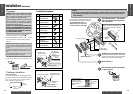
❐ Connect All Leads
Now that you have identified all the wires in the car, you
are ready to begin connecting them to the stereo unit
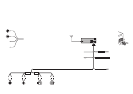
wires. The wiring diagram (\ page 30) shows the proper
connections and color coding of the leads.
We strongly recommend that you test the unit before
making a final installation.
You can set the unit on the floor and make temporary con-
nections to test the unit. Use electrical tape to cover all
exposed wires.
Ground
Connect the black ground lead of the power connector to
the metal car chassis.
Speakers
Connect the speaker wires. See the wiring diagram
(\ page 30) for the proper hookups. Follow the diagram
carefully to avoid damaging the speakers and the stereo
unit.
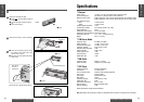
The speakers used must be able to handle more than 50
W (CQ-C1200U/C1120U)/45 W (CQ-C1110U/C1100U) of
audio power. If using an optional audio amplifier, the
speakers should be able to handle the maximum amplifier
output power. Speakers with low input ratings can be
damaged. Speaker impedance should measure 4–8 Ω,
which is typically marked on most speakers. Lower or
higher impedance speakers will affect output and can
cause both speaker and stereo unit damage.
Motor Antenna
Connect the car motor antenna lead to the dark blue
motor antenna relay control lead.
(Do not confuse the antenna lead with blue/white stripe
lead for a power amplifier.)
Battery
Connect the yellow battery lead to the correct radio wire
or to the battery fuse port on the fuse block.
Antenna
Connect the antenna by plugging the antenna lead into the
antenna receptacle.
Equipment
Connect any optional equipment such as an amplifier,
according to the instructions furnished with the equip-
ment. Leave about 12" (30 cm) of distance between the
speaker leads/amplifier unit and the antenna/antenna
extension cord. Read the operating and installation
instructions of any equipment you will connect to this
unit.
Power
Connect the red power lead to the correct car radio wire
or to the appropriate fuse port on the fuse block.
If the stereo unit functions properly with all these connec-
tions made, disconnect the wires and proceed to the final
installation.
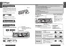
❐ Final Installation
Lead Connections
Connect all wires, making sure that each connection is
insulated and secure. Bundle all loose wires and fasten
them with tape so they will not fall down later. Now insert
the stereo unit into the mounting collar.
Congratulations! After making a few final checks, you’re
ready to enjoy your new auto stereo system.
❐ Final Checks
1. Make sure that all wires are properly connected and
insulated.
2. Make sure that the stereo unit is securely held in the
mounting collar.
3. Turn on the ignition to check the unit for proper opera-
tion.
If you have difficulties, consult your nearest authorized
professional installer for assistance.