


47
Installation
Installation
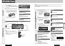
CQ-CB8901U
46
Installation
CQ-CB8901U
Warning
¡DO NOT INSTALL THE MONITOR IN A LOCATION
WHICH OBSTRUCTS DRIVING, VISIBILITY OR
WHICH IS PROHIBITED BY APPLICABLE LAWS
AND REGULATIONS. If the monitor is installed
in a location which obstructs forward visibility
or operation of the air bag or other safety equip-
ment or which interferes with operation of the
car, it may cause an accident.
¡Never use bolts or nuts from the car's safety
devices for installation. If bolts or nuts from the
steering wheel, brakes or other safety devices are
used for installation of the monitor, it may cause
an accident.
¡Attach the wires correctly. If the wiring is not cor-
rectly performed, it may cause a fire, failure of
electrical equipment and-or an accident. In partic-
ular, be sure to run and secure the lead wire so
that it does not get tangled with a screw or the
moving portion of a seat rail.
¡Use with 12 V DC negative ground car. This unit
is only for use with a 12 V DC negative ground
car. It cannot be used in large trucks or diesel
cars which are 24 V DC cars. If it is used in the
wrong type of car, it may cause a fire or an acci-
dent.
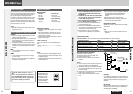
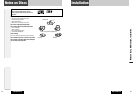
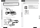
❏ Required Tools
You’ll need a screwdriver and the following:
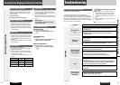
❏ Dashboard Specifications
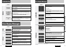
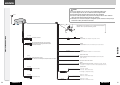
❏ Identify All Leads
The first step in installation is to identify all the car
wires you’ll use when hooking up your LCD monitor.
As you identify each wire, we suggest that you label
it using masking tape and a permanent marker. This
will help avoid confusion when making connections
later.
Note: Do not connect the power connector to the
display unit until you have made all connections. If
there are no plastic caps on the hooking wires, insu-
late all exposed leads with electrical tape until you
are ready to use them. Identify the leads in the fol-
lowing order.
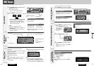
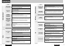
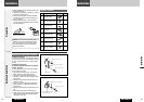
Power Lead
If your car has a radio or is pre-wired for one:
Cut the connector wires one at a time from the plug
(leaving the leads as long as possible) so that you
can work with individual leads. Turn the ignition on
to the accessory position, and ground one lead of
the test bulb to the chassis.
Touch the other lead of the test bulb to each of the
exposed wires from the cut radio connector plug.
Touch one wire at a time until you find the outlet that
causes the test bulb to light.
Now turn the ignition off and then on. If the bulb
also turns off and on, that outlet is the car power
lead.
If your car is not wired for an audio unit:
Go to the fuse block and find the fuse port for radio
(RADIO) accessory (ACC) or ignition (IGN).
Battery Lead
If your stereo unit has a yellow lead, you will need to
locate the car's battery lead. Otherwise you may
ignore this procedure. (The yellow battery lead pro-
vides continuous power to maintain a clock or other
functions.)