


36
Item Adjustments
INPUT lock
Off PC INPUT1 INPUT2 INPUT3
Locks the input switch operation.
Notes:
• Only the adjusted signal is displayed (see page 13).
• Signal can be displayed when the Terminal board is installed.
• Input switch can be used when this is set to “Off”.
• In two screen display mode, if anything other than “Off” is set, the value will be fi xed as the value input in
the single screen display mode.
• When a dual input terminal board is attached, A or B is displayed depending on the selected input signal.
(Ex. INPUT1A, INPUT1B)
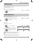
Button lock
Off MENU&ENTER On
Off: All the buttons on main unit can be used.
MENU&ENTER: Locks
MENU
and
ENTER/
buttons on main unit.
On: Locks all the button on main unit.
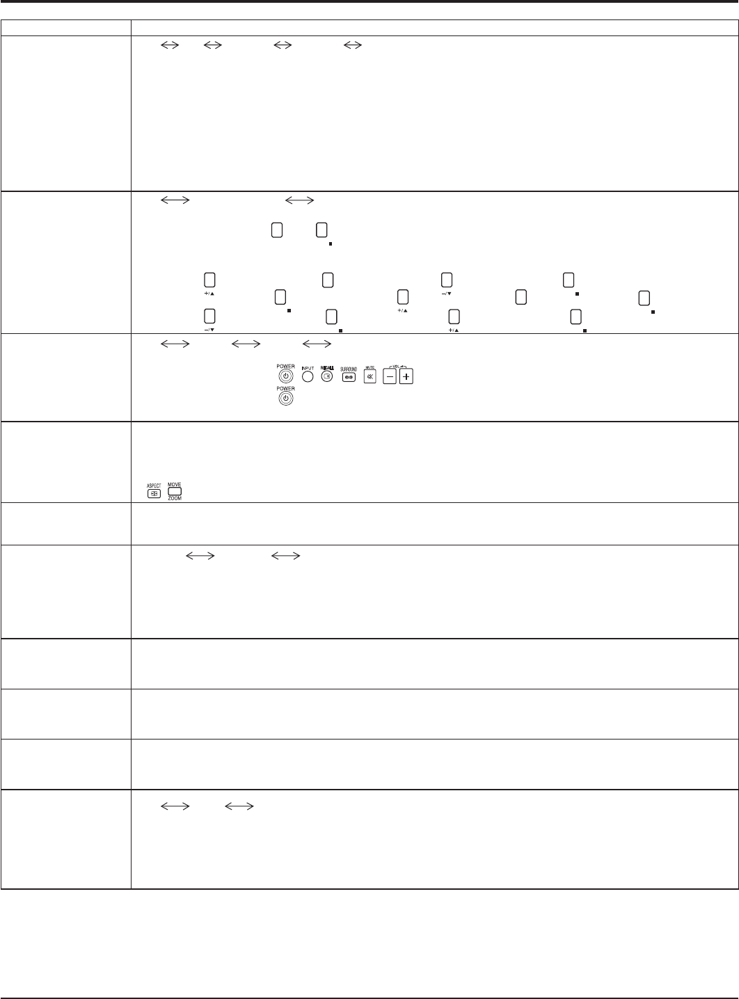
Sets Button lock with the unit buttons in the following procedure.
Off: Press
four times→Press
INPUT
four times→Press four times→Press
ENTER/
MENU&ENTER: Press
ENTER/
four times→Press four times→Press
INPUT
four times→Press
ENTER/
On: Press four times→Press
ENTER/
four times→Press four times→Press
ENTER/
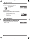
Remocon User level
Off User1 User2 User3
Off: You can use all of the buttons on the remote control.
User1:
You can only use , , , , , buttons on the remote control.
User2: You can only use
button on the remote control.
User3:
Locks all the buttons on remote control.
Advanced PIP
Off: Sets normal two screen display mode (see page 17).
On: Sets Advanced PIP mode (see page 18).
Notes:
• When “INPUT lock” is “On”, you cannot use all the two screen display functions.
•
, buttons are unavailable during Advanced PIP mode operation.
Off-timer function
Enable: Enables the “Off-timer function”.
Disable: Disables the “Off-timer function”.
Note: When “Disable” is set, the Off-timer is cancelled.
Initial Power Mode
Normal Standby On
Sets the power mode of the unit for when the power recovers from failure or after plugging off and in again.
Normal: Power returns in as the same state as before the power interruption.
Standby: Power returns in standby mode. (Power Indicator : red/orange)
On: Power returns in power On. (Power Indicator : green)
Note:
When using multiple displays, “Standby” is preferred to be set in order to reduce a power load.
ID select
Sets panel ID number when panel is used in “Remote ID” or “Serial ID”.
Set value range: 0 - 100
(Standard value: 0)
Remote ID
The setting of this menu is valid only when using ID remote control.
Off: Disables ID remote control functions. You can use normal remote control operations.
On: Enable ID remote control functions.
Serial ID
Sets the panel ID Control.
Off: Disables external control by the ID.
On: Enables the external control by the ID.
Slot Power
Off Auto On
Off: Power is not transmitted to the slot power.
Auto: Power is transmitted to the slot power only when main power is on.
On: Power is transmitted to the slot power when main power is on or in the standby state.
Note: In some cases, power is transmitted to the slot power when main power is on or in the standby state
regardless of the slot power setting.
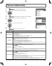
Options Adjustments