5
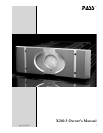
X260.5 Owners Manual
Looking at the rear panel you will see the IEC 320 AC power cord
receptacle, a mains power switch, two pairs of output connectors, a
pair of binding post connectors for remote turn-on, one RCA input
connector and one XLR balanced input connector.
Make sure that the mains power switch is off (down). Plug the AC
cord into the back of the amplifier, and then into the wall. Then turn
the breaker switch on (up). The lights in your house may blink when
the power supply charges the capacitors; this is normal. This mains
power switch is not to be used as a safety disconnect during servicing
and is not a substitute for unplugging the power cord.
On the front panel, the “Standby” LED indicator should be glowing
blue, indicating that the power is on. The “Power” LED should not
be on. If the “Power” LED is on, don’t get excited, just use the front
panel stand-by button to go into stand-by mode, with the “Standby”
LED on and the “Power “ LED off.
OK, so the amplifier is sitting there in stand-by mode with just the
single blue LED lit. No speaker connected, as yet. You can go ahead
and connect the source and speakers. Some speaker cables are very
difficult to work with due to physical size and construction, make sure
the speaker connections do not short together. It is recommended
that you connect the speaker ends of these cables first.
Some powered subwoofers require an audio signal ground reference
and their makers may suggest that a black speaker terminal is where
this voltage reference might be found. On complementary designs,
which would be typical of all power amps produced by Pass Laborato-
ries™, this is an incorrect and unsafe assumption. On all Pass Labo-
ratories™ power amplifiers a reference of 0 volts will be found only at
pin 1 of the XLR input or at the shell of the RCA input.
Reference connections for these devices require special consideration
when used with our product. If you have such a device, and wish to
use it with our product, please contact our Foresthill, California fac-
tory for specific instructions.... you have been warned.
XLR input connector showing
proper placement of jumper pin
for use with single-ended (RCA)
input.
Note: On X260.5 XLRs are
upside down.


