


17
2
3
2a
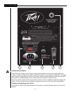
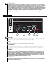
Second, unscrew the screws holding the clear switch protector on the voltage selector switch (1) just a little, just
enough to allow removal of the clear switch protector. The screws DO NOT need to be unscrewed very far.
Third, remove the clear plastic protector from the voltage selector switch.
Fourth, using a small flat blade screwdriver, push the red selector switch slide plate to the other side from where
it was. The voltage that is now visible on the red slide plate is the one you have selected.
Fifth, replace the clear plastic protector underneath the two loosened screws, and tighten one down while
holding the clear plastic protector in place. Tighten the other screw down, and make sure both screws are tight.
Sixth, the fuse should be changed to the correct amperage rating. For an input power voltage range from
100VAC to 120VAC, use a 6.3 amp rated, 250V 5 x 20 mm cartridge type time-delay fuse, which conforms to
the international fuse classification “T6.3AL”. For an input power voltage range of from 220VAC to 240VAC,
use a 3.15 amp rated, 250V 5 x 20 mm cartridge type time-delay fuse, which conforms to the international fuse
classification “T3.15AL”.
The IEC power cord that is correct for your locale can now be plugged into the IEC receptacle (2), and the Power
switch (3) activated to turn on the powered PV
®
115D speaker system.
IEC POWER CORD CONNECTION
This receptacle is for the IEC line cord (normally supplied with the correct pins and wiring for your locale) that
provides AC power to the unit.
Please read this guide carefully to ensure your personal safety as well as the safety of your equipment.
Never break off the ground pin on any equipment. It is provided for your safety. If the outlet used does not have
a ground pin, a suitable grounding adapter should be used and the third wire should be grounded properly. To
prevent the risk of shock or fire hazard, always be sure that the mixer and all other associated equipment are
properly grounded.
FUSE
The unit is AC power line fuse protected from overloads and fault conditions with a slow-blow 5 x 20mm 250V fuse.
This fuse is located within the cap of the fuse enclosure just to the left of the ON-OFF switch. If the fuse fails, THE
FUSE MUST BE REPLACED WITH THE SAME TYPE AND VALUE IN ORDER TO AVOID DAMAGE TO THE EQUIPMENT
AND TO PREVENT VOIDING THE WARRANTY!
The fuse in the PV
®
115D can be replaced with a time-delay type 5 x 20 mm size 250V rated fuse.
For 100-120VAC operation, a fuse rated at 6.3 amps should be used. In the USA, types GDC, GMC, 215, 218, and
477 cartridge-style 5 x 20 mm size fuses with a 6.3 amp 250V rating can be used.
For 220-240VAC operation, a fuse rated at 3.15 amps and 250V should be used, which conforms to the
international fuse classification "T3.15AL".
If the unit continues to blow replacement fuses, do not keep replacing them it should be taken to a qualified
service center for repair.
To replace the fuse, be sure to remove the IEC power cord from the IEC socket (2).
Remove the cap to the fuse enclosure (2a) using a flat blade screwdriver tip inserted into the fuse cap slot. Push
the cap in and turn the cap CCW and pull the cap out. The blown fuse should come out with the cap. Remove the
blown fuse and replace it with the proper type per instructions previously supplied. Then, once the new fuse has
been put in place, re-insert the fuse enclosure cap, push in and turn the cap CW, and make sure it is fully seated.
Before re-attaching the IEC power cord to the IEC socket, make sure the Power switch is in the OFF position, so that
intermittent contact of the IEC cord while it is being connected will not unduly stress the amplifier or the fuse. Now
re-attach the IEC power cord, and you can then use the Power switch to turn the unit on.
ON-OFF SWITCH
This rocker switch supplies AC power to the PV
®
115D when switched to the ON position.