


REAR SURROUND SPEAKERS
VIDEO OUT
AUDIO OUT
+
–
+
–
R
L
L
R
FIXED
VAR
ANT A/CABLE
75 ⍀ UHF/VHF
Y
INPUTS
P
B
P
R
S-VIDEO
VIDEO
AUDIO
AUX 1AUX 2
R
L
1
CABLE OUT
CABLE IN
ANTENNA
OUT
ANTENNA
IN
VIDEO AUDIO
IN
IN
OUT OUT
2
RL
VIDEO OUT
AUDIO OUT
L
R
FIXED
VAR
ANT/CABLE
75 ⍀ UHF/VHF
INPUTS
VIDEO
AUDIO
AUX 1 AUX 2
R
L
3
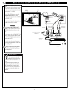
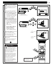
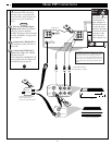
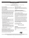
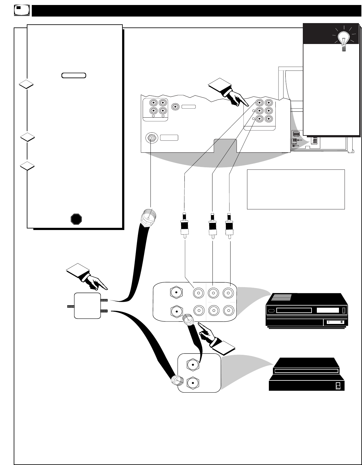
MORE PIP CONNECTIONS
T
he following example is for an
alternative PIP connection
hookup using an external Cable
Converter Box and a VCR (as the
picture source for the PIP win-
dow).
First use an optional signal
splitter and connect the original
cable TV signal to both the
CABLE IN on the Cable Converter
and the ANTENNA A plug on the
rear of the TV.
Connect the CABLE OUT on
the Converter to the ANT. IN on
the VCR.
Connect the VIDEO OUT
jack on the VCR to the VIDEO
IN jack on the TV.
Also connect the AUDIO OUT (R
and L) jacks from the VCR to the
AUDIO IN jacks on the TV.
SIGNAL
SPLITTER
CABLE TV CONVERTER
VCR
1
2
3
STOP
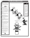
Remember
to use the Cable TV
Converter Box to
select channels for
PIP, the VCR must
be set to the same
channel as the chan-
nel selection switch
on the rear of the
Cable Converter
(either channel 3 or
4).
SMART
HELP
BEGIN
45
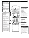
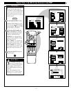
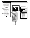
The ANTENNA signal input supplies the TV’s Main
screen picture, and the AUX 1 VIDEO Input connec-
tion from the VCR serves as the picture source for
PIP. Be sure to set the TV’s PIP SOURCE SELECT
control to the “AUX 1 VIDEO” mode in order to dis-
play the Audio/Video Input signals within the PIP
window.
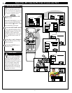
Contact the Parts Information
Center 1 800 851-8885
to order any optional accessories
REAR OF TV
AUDIO VIDEO CABLES
(RCA Plug Cables - optional)