


9397 750 13022 © Koninklijke Philips Electronics N.V. 2004. All rights reserved.
Preliminary data sheet Rev. 02 — 26 April 2004 13 of 27
Philips Semiconductors
TEA5880TS
Integrated FM stereo radio IC for host processor tuning
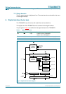
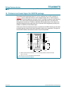
8.2 Accessing the TEA5880TS
Access to the TEA5880TS can be achieved via the 3-wire bus. At the host side, the R/W
and CLOCK are output signals, while the DATA signal is bidirectional.
When powered up, the host should initialize the 3-wire bus in the host read mode as
follows:
1. Set (at host side) the DATA line into input mode
2. R/W set to LOW
3. CLOCK set to LOW.
Note: Use the following sequence for changing read/write mode:
1. To change from host read mode to host write mode proceed as follows:
a. Keep the CLOCK signal LOW
b. Set the R/W signal to HIGH (write mode)
c. Set the DATA pin (of the application controller) into output mode.
2. To change from host write mode to host read mode proceed as follows:
a. Keep the CLOCK signal LOW
b. Set the DATA pin (of the application controller) into input mode
c. Set R/W to LOW (input mode).
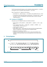
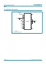
8.3 Writing to the TEA5880TS
Writing to the TEA5880TS is achieved with a 15-bit data pattern:
• D[14:11]: 4-bit register address
• D[10:0]: 11-bit register data.
The data pattern is sent serially to the TEA5880TS as follows:
1. Drive R/W pin HIGH to set the TEA5880TS in input mode
2. Drive the DATA pin to correct level
3. Generate positive edge of CLOCK (driving CLOCK into LOW-to-HIGH transition)
4. Delay some time to meet the data hold time requirement
5. Driving CLOCK into HIGH-to-LOW transition
6. Repeat step (2) to (5) 15 times to shift the 15-bit data pattern into the TEA5880TS
7. Drive R/W pin LOW; this signals the TEA5880TS to latch the data into the correct
register.
Note: The application should shift the LSB out first.