


9397 750 13022 © Koninklijke Philips Electronics N.V. 2004. All rights reserved.
Preliminary data sheet Rev. 02 — 26 April 2004 19 of 27
Philips Semiconductors
TEA5880TS
Integrated FM stereo radio IC for host processor tuning
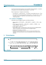
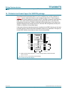
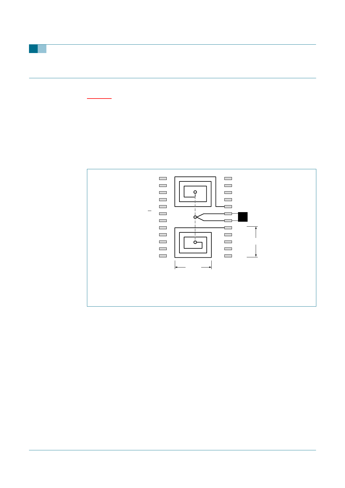
14. Printed-circuit board layout for SSOP24 package
The printed-circuit board traces from LL1 to V
CC1
and from V
CC1
to LR1 as shown in
Figure 10, are to create two inductors, each of approximately 38 nH. These inductors,
together with internal capacitors, form part of the LC oscillator to determine the FM tuning
band. If the value of the inductors becomes much greater than 38 nH, the whole FM
tuning band (normally from 76 MHz to 108 MHz) will be shifted lower. If the value of the
inductors becomes much smaller than 38 nH, the whole FM tuning band (normally from
76 MHz to 108 MHz) will be shifted higher.
If the layout of the two inductance traces is not preferred, two SMD inductors can be used
to replace the two printed-circuit board inductance traces as an alternative. The layout of
the two SMD inductors should be as close to the pins as possible.
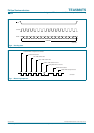
(1) Width of printed-circuit board trace = 0.15 mm; spacing between printed-circuit board
trace = 0.15 mm.
(2) Pins 14, 15, 16, 21, 22 and 23 are not connected.
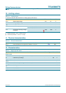
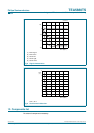
Fig 10. Printed-circuit board layout.
001aaa675
GND
RFIN
RFGND
V
CCD
AUDR
GND
n.c.
n.c.
n.c.
LR1
reserved
n.c.
n.c.
GND
LL1
MPX
3.5 mm
3.5 mm
R/W
CLOCK
DATA
AUDL
LED
V
CC1
V
CC1
V
CCA