


xxxx xxxxxxxxxxxxxxxxxxxxxxxxxxxxxx x xxxxxxxxxxxxxx xxxxxxxxxx xxx xxxxxx xxxxxxxxxxxxxxxxxxxxxxx xxxxxxxxxxxxxxxxxxxxxx
xxxxx xxxxxx xx xxxxxxxxxxxxxxxxxxxxxxxxxxxxx xxxxxxxxxxxxxxxxxxxxxx xxxxxxxxxxx xxxxxxx xxxxxxxxxxxxxxxxxxx
xxxxxxxxxxxxxxxx xxxxxxxxxxxxxx xxxxxx xx xxxxxxxxxxxxxxxxxxxxxxxxxxxxxxxx xxxxxxxxxxxxxxxxxxxxxxxx xxxxxxx
xxxxxxxxxxxxxxxxxxxxxxxxxxxxxxxxxxxxxxxxxxxxxx xxxxxxxxxxx xxxxx x x
9397 750 13022 © Koninklijke Philips Electronics N.V. 2004. All rights reserved.
Preliminary data sheet Rev. 02 — 26 April 2004 4 of 27
Philips Semiconductors
TEA5880TS
Integrated FM stereo radio IC for host processor tuning
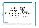
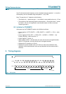
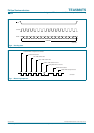
5. Block diagram
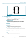
Depending on the antenna design the filter components at pins 1 and 2 may not be necessary. The only two remaining coils connected to pin
17 to 20 can be replaced by printed-circuit board traces that will fit underneath the TEA5880TS resulting in a design without any external
components; see Section 14 for details on the printed-circuit board coils.
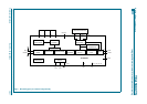
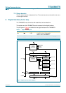
Fig 1. Block diagram.
001aaa665
QUADRATURE
MIXER
STABILISATOR
QUADRATURE
OSCILLATOR
TUNING
SYSTEM
SELECTIVITY DEMODULATOR
POWER
SWITCH
STEREO
DECODER
DE-EMPHASIS
50/75 µs
DIGITAL
INTERFACE
MICROCONTROLLER
DE-EMPHASIS
15 kHz
MIXER
LEVEL VOLTAGE
GENERATOR
10
TEA5880TS
11
9
5
68 7
2117 18 19 20
1
2
4 3, 13, 24
V
CCA
RFIN
RFGND
LR1 V
CC1
V
CC1
LL1
reserved
R/W CLOCK
AUDL
AUDR
MPX
DATA
V
CCD
GND LED n.c.
12 14, 15, 16, 22, 23