


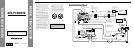

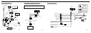

<ENGLISH>Connecting the Units
Multi-CD player
(sold separately)
IP-BUS-RCA-Interconnector
(CD-RB20) (sold separately)
Blue
Blue
20 pin cable
(supplied)
DVD Navigation Unit
(e.g.AVIC-9DVD)
(sold separately)
Connection box
(supplied with the DVD
Navigation Unit)
RCAcables
(sold separately)
To audio outputs
To video output
Head Unit
(sold separately)
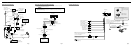
Green
Red
3m
Not used.
40 cm
40 cm
Blue
Voice guidance speaker
(supplied)
Yellow
(VIDEO INPUT)
This product
3m
Red
RCAcables
(supplied)
16 cm
6m
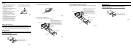
When Connecting the Head Unit
Fig. 3 Fig. 4
When Using a Display Connected Rear Video Output
This product’s rear video output is for connection of a display to enable passengers in the
rear seats to watch the DVD or Video CD.
WARNING
• NEVER install the display in a location that enables the Driver to watch the DVD or
Video CD while Driving.
This product
Display with RCA
input jacks
RCAcable (supplied)
To audio inputs
To video input
RCAcable (sold separately)
Yellow (REAR
VIDEO OUTPUT)
White (audio output (Left))
Red (audio output (Right))
6m
16 cm
16 cm
16 cm
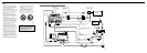
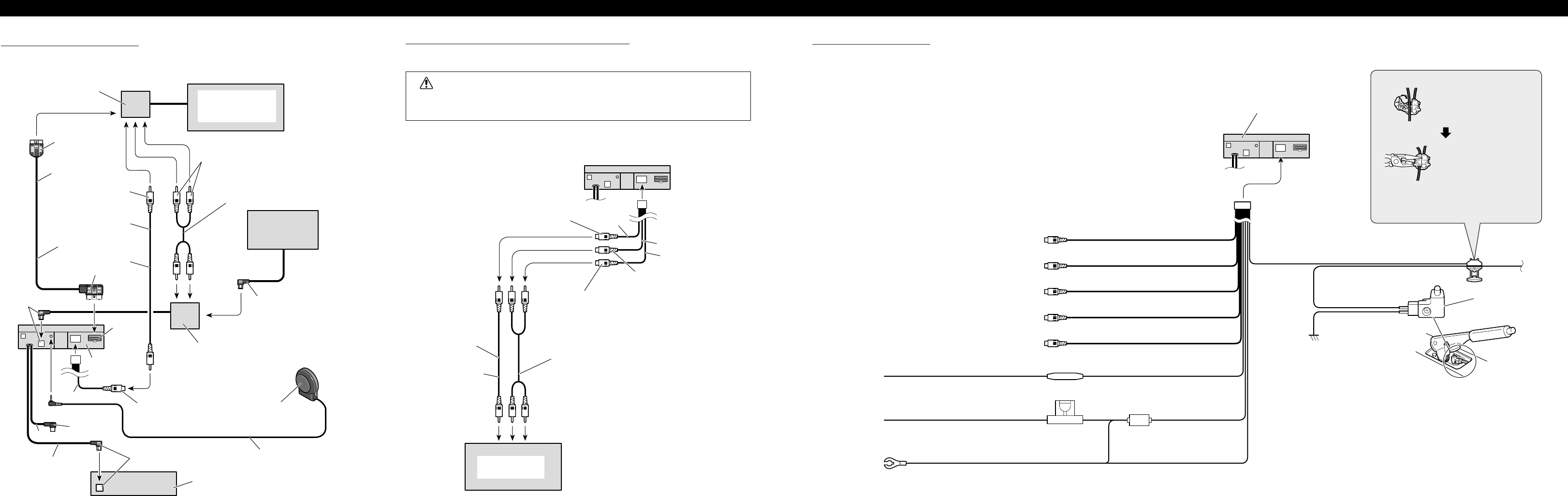
Light green
Used to detect the ON/OFF status of the parking brake.
This lead must be connected to the power supply side
of the parking brake switch.
Parking brake switch
Red
To electric terminal controlled by ignition
switch (12V DC) ON/OFF.
Fuse resistor
Fuse holder
Black (ground)
To vehicle (metal) body.
Power supply side
Ground side
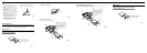
Connection method
2.Clamp firmly with
needle-nosed pliers.
Clamp the parking brake
switch power supply side
lead.
Note:
• The position of the parking brake switch depends
on the vehicle model. For details, consult the
vehicle Owner’s Manual or dealer.
This Product
1.
Yellow
To terminal always supplied with power
regardless of ignition switch position.
Yellow (rear video output)
(REARVIDEO OUTPUT)
White (audio output (Left))
(REAR OUTPUT)
Red (audio output (Right))
(REAR OUTPUT)
Yellow (video input)
(VIDEO INPUT)
Yellow (AVM output)
(AVM OUTPUT)
16 cm
16 cm
16 cm
16 cm
16 cm
Connecting the Power Cord
Fig. 5