


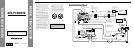


<ENGLISH>Installation
Note:
• Before finally installing the unit, connect the
wiring temporarily, making sure it is all connected
up properly, and the unit and the system work
properly.
• Use only the parts included with the unit to ensure
proper installation. The use of unauthorized parts
can cause malfunctions.
• Consult with your nearest dealer if installation
requires the drilling of holes or other modifications
of the vehicle.
• Install the unit where it does not get in the driver’s
way and cannot injure the passenger if there is a
sudden stop, like an emergency stop.
• Do not place the display in a position where it will
impede the driver’s visibility or affect the opera-
tion of your vehicle’s air bags.
• The semiconductor laser will be damaged if it
overheats, so don’t install the unit anywhere hot
— for instance, near a heater outlet.
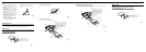
• If installation angle exceeds 30° from horizontal,
the unit might not give its optimum performance.
(Fig. 6)
Fig. 6
30°
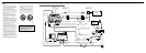
7 When the installation space is not very deep
When installing in a shallow space, secure with side brackets (small). In this case, stick con-
ceal tape on parts that protrude from the dashboard.
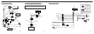
Fig. 10
Holder
After inserting the holder into the dash-
board, then select the appropriate tabs
according to the thickness of the dash-
board material and bend them.
(Install as firmly as possible using the
top and bottom tabs. To secure, bend
the tabs 90 degrees.)
182
53
Rubber bush
Screw
Dashboard
Attach screw
Side bracket
(small)
Conceal tape
2. Install side brackets. (Fig. 8)
Fig. 8
3. Fastening the unit. (Fig. 9)
As a rule, secure with side brackets (large).
Fig. 9
Holder
After inserting the holder into the dash-
board, then select the appropriate tabs
according to the thickness of the dash-
board material and bend them.
(Install as firmly as possible using the
top and bottom tabs. To secure, bend
the tabs 90 degrees.)
182
53
Rubber bush
Screw
Dashboard
Side bracket
(large)
Attach screw
Flush surface screw (5 × 6 mm)
Side bracket
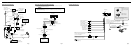
DIN Front/Rear-mount
This unit can be properly installed either from “Front” (conventional DIN Front-mount) or
“Rear” (DIN Rear-mount installation, utilizing threaded screw holes at the sides of unit
chassis). For details, refer to the following illustrated installation methods.
DIN Front-mount
Installation with the rubber bush
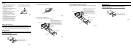
1. Remove the frame. (Fig. 7)
Fig. 7
Frame
Pull out to remove the frame.
(When reattaching the frame, point the
side with a groove downwards and
attach it.)
DIN Rear-mount
Installation using the screw holes on the side of the unit
1. Remove the frame. (Fig. 11)
Fig. 11
Frame
Pull out to remove the frame.
(When reattaching the frame, point the
side with a groove downwards and
attach it.)