


65
DEH-2130R,2100R
+
≠
+
≠
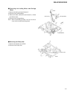
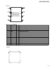
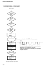
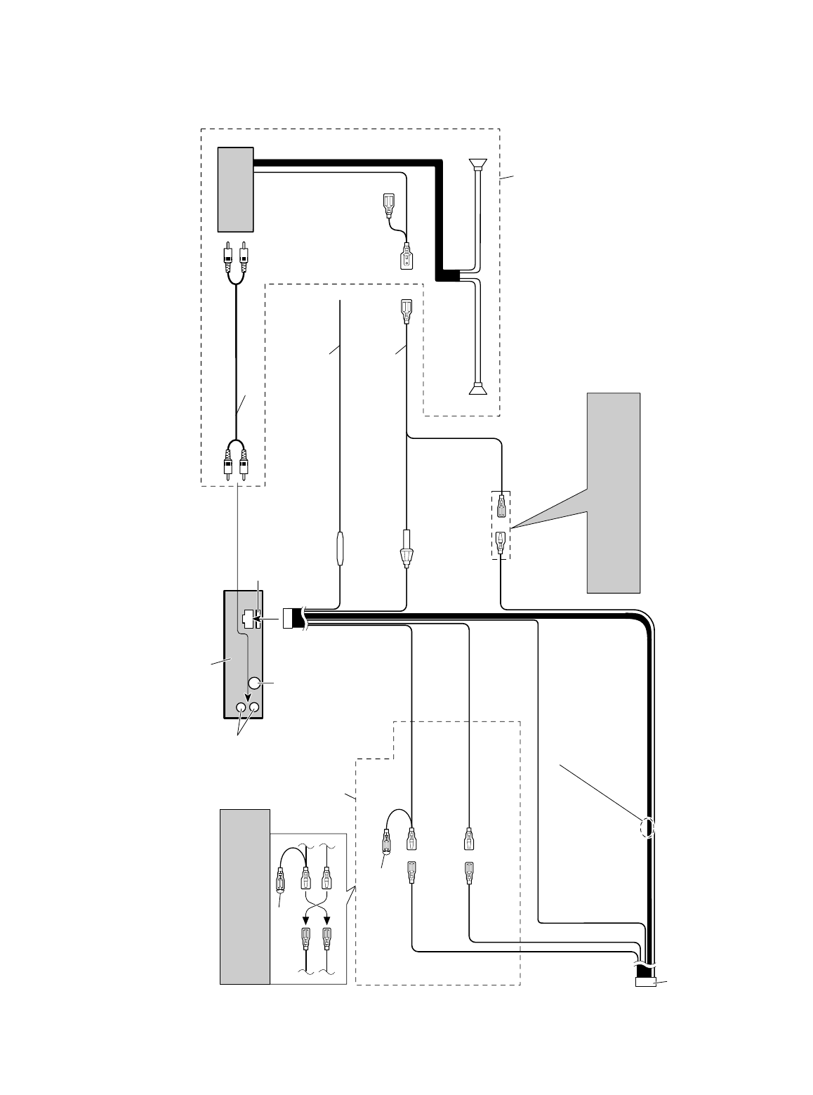
Note:
Depending on the kind of vehicle, the func-
tion of 3* and 5* may be different. If this is
the case, be sure to connect 2* to 5* and 4* to
5.
4*
5*
3*
1*
2*
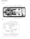
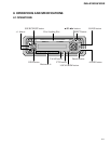
1. This product
2. Rear output
3. Antenna jack
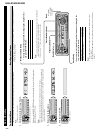
6. Connect leads of the same
color to each other.
7. Cap (1*)
When not using this terminal,
do not remove the cap.
8. Yellow (3*)
Back-up
(or accessory)
9. Yellow (2*)
To terminal always supplied
with power regardless of
ignition switch position.
10. Red (5*)
Accessory
(or back-up)
11. Red (4*)
To electric terminal con-
trolled by ignition switch
(12 V DC) ON/OFF.
19. Fuse holder
12. Black (ground)
To vehicle (metal) body.
13. ISO connector
Note:
In some vehicles, the ISO connector may
be divided into two. In this case, be sure
to connect to both connectors.
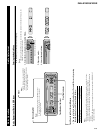
18. Yellow/black
If you use a cellular telephone, connect it via
the Audio Mute lead on the cellular telephone.
If not, keep the Audio Mute lead free of any
connections.
17. Fuse resistor
14. Speaker leads
White : Front left +
White/black : Front left ≠
Gray : Front right +
Gray/black : Front right ≠
Green : Rear left +
Green/black : Rear left ≠
Violet : Rear right +
Violet/black : Rear right ≠
22. Blue/white (6*)
23. Blue/white (7*)
To Auto-antenna relay control terminal.
(Max. 300 mA 12 V DC.)
24.
The pin position of the ISO connector will differ
depends on the type of vehicle. Connect 6* and 7*
when Pin 5 is an antenna control type. In another
type of vehicle, never connect 6* and 7*.
26. Perform these connections when using
a different amp (sold separately).
25. Rear speaker
25. Rear speaker
21. System remote control
20. Blue/white
To system control terminal of the power amp.
(Max. 300 mA 12 V DC.)
15. Connecting cords with
RCA pin plugs (sold separately)
16. Power amp
(sold separately)
4. Fuse