


9
Connecting the System
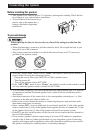
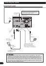
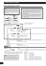
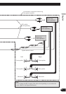
Connecting the power cord (1)
Connect leads of the same
colour to each other.
Cap (*1)
When not using this terminal,
do not remove the cap.
ISO connector
*1
*2
*4
*3
*5
Yellow (*2)
To terminal always supplied
with power regardless of
ignition switch position.
Red (*4)
To electric terminal controlled
by ignition switch (12 V DC)
ON/OFF.
Yellow (*3)
Back-up
(or accessory)
Red (*5)
Accessory
(or back-up)
Black (earth)
To vehicle (metal) body.
Orange/white
To lighting switch terminal.
Note:
In some vehicles, the ISO connector
may be divided into two. In this case,
be sure to connect to both connectors.
Note:
Depending on the kind of vehicle, the
function of *3 and *5 may be different.
In this case, be sure to connect *2 to *5
and *4 to *3.
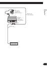
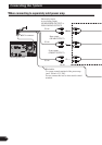
Speaker leads
White: Front left +
White/black: Front left ≠
Grey: Front right +
Grey/black: Front right ≠
Green: Rear left + or Subwoofer + (*9)
Green/black: Rear left ≠ or Subwoofer ≠ (*9)
Violet: Rear right + or Subwoofer + (*9)
Violet/black: Rear right ≠ or Subwoofer ≠ (*9)
Yellow/black
If the vehicle can send a mute signal to this terminal,
the mute function can be activated on this navigation
system when the terminal is connected to *8.
Notes:
• When a subwoofer (*9) is connected to this navigation
system instead of a rear speaker, change the rear output
setting in the Initial Setting. (Refer to the Operation
Manual.) The subwoofer output of this navigation sys-
tem is monaural.
• When using a subwoofer of 70W (2Ω), be sure to con-
nect with violet and violet/black leads of this naviga-
tion system. Do not connect anything with Green and
Green/Black leads.