


4 Press M.C. and hold untilthe customizing
illumination color setting appears in the dis-
play.
5 Press M.C. to select the primarycolor.
R (red)—G (green)—B (blue)
6 Turn M.C. to adjust the brightness level.
Adjustment range: 0 to 60
# You cannot selecta level below10 for all threeof
R (red),G (green), andB (blue) at thesame time.
# You can alsoperform the sameoperation on
other colors.
Notes
! You cannot create a custom illumination
color when SCAN or a set of colors (WARM,
AMBIENT,orCALM) is selected.
! You can create custom illumination colors
for both KEY COLOR and DISP COLOR.
Switching the dimmer setting
You can adjust the brightness of illumination.
% Press and hold
.
Using an AUX source
1 Insert the stereo mini pluginto the AUX
input jack.
2 Press SRC/OFF to select AUX asthe
source.
Note
AUX cannot be selected unless theauxiliary set-
ting is turned on. For more details, refer to AUX
(auxiliary input) on page 11.
Turning the clock display on
or off
% Press to turn the clock display on or
off.
# The clockdisplay disappears temporarilywhen
you perform otheroperations, but the clockdisplay
appears againafter 25seconds.
Connections
WARNING
! Use speakers over 50 W (output value)and
between 4 W to 8 W (impedance value).Do
not use 1 W to 3 W speakers forthis unit.
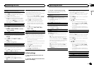
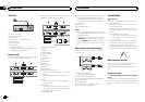
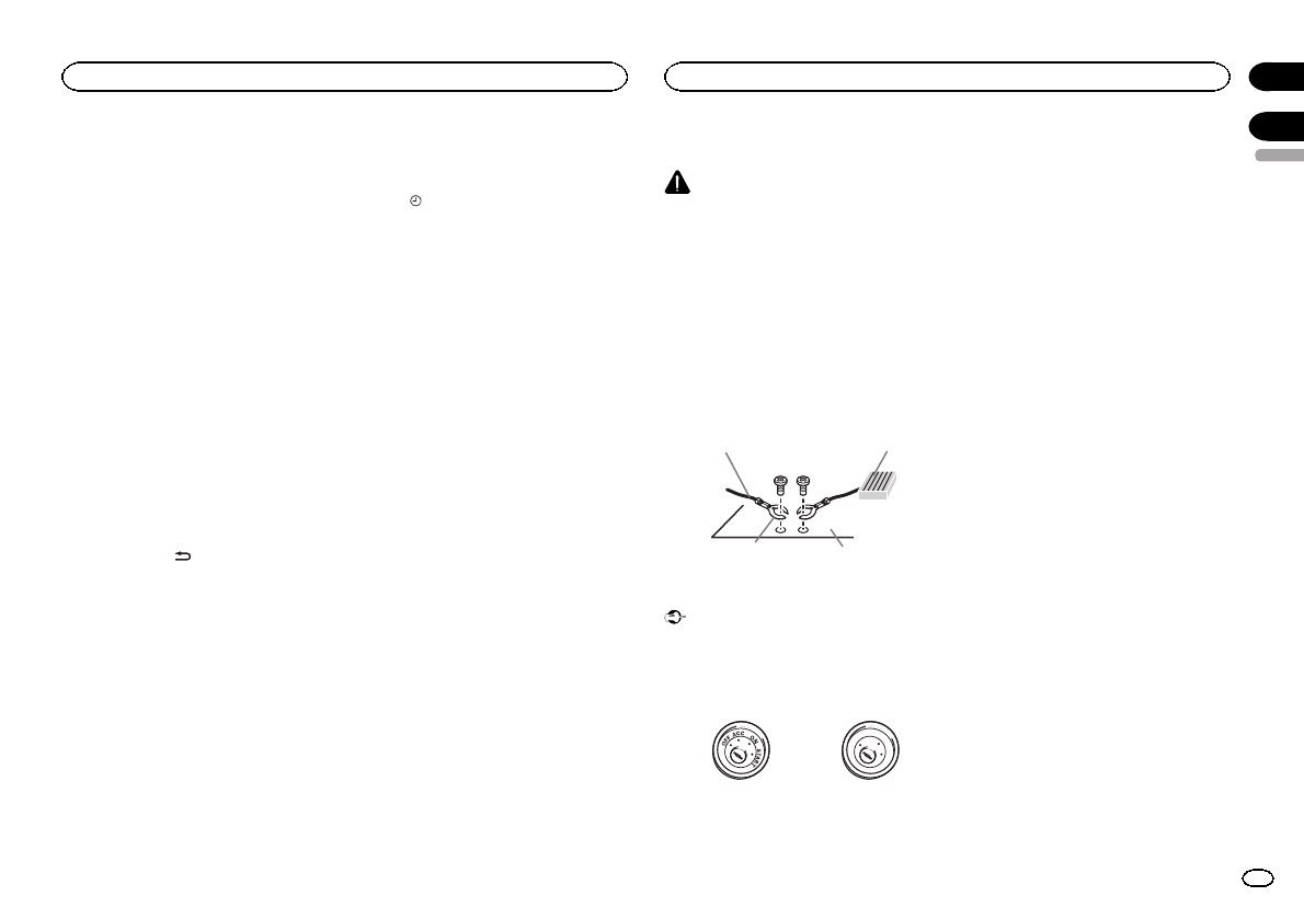
! The black cable is ground. When installing
this unit or power amp (sold separately),
make sure to connect the ground wirefirst.
Ensure that the ground wire is properly con-
nected to metal parts of the car’s body. The
ground wire of the power amp and the oneof
this unit or any other device must becon-
nected to the car separately with different
screws. If the screw for the ground wire loos-
ens or falls out, it could result in fire, genera-
tion of smoke or malfunction.
Ground wire
Metal parts of car’s bod
y
POWER AMP
Other devices
(Another electronic
device in the car)
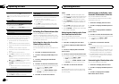
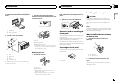
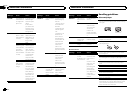
Important
! When installing this unit in a vehicle without
an ACC (accessory) position on the ignition
switch, failure to connect the red cableto the
terminal that detectsoperation of the ignition
key may result in battery drain.
O
N
S
T
A
R
T
O
F
F
ACC position NoACC position
! Use this unit with a 12-volt battery and nega-
tive grounding only. Failureto do so may re-
sult in a fire or malfunction.
! To prevent a short-circuit, overheatingor mal-
function, be sure to follow thedirections
below.
— Disconnect thenegative terminal ofthe bat-
tery before installation.
— Secure thewiring with cableclamps or adhe-
sive tape.Wrap adhesivetape around wiring
that comesinto contact withmetal parts to
protect thewiring.
— Placeall cables away frommoving parts,
such asthe shift lever andseat rails.
— Placeall cables away fromhot places, such
as nearthe heater outlet.
— Donot connect theyellow cable tothe battery
by passingit through thehole to the engine
compartment.
— Coverany disconnected cable connectors
with insulatingtape.
— Do notshorten any cables.
— Nevercut the insulation ofthe power cableof
this unitin order to sharethe power with
other devices.The current capacityof the
cable islimited.
— Usea fuse of therating prescribed.
— Never wirethe negative speakercable directly
to ground.
— Neverband together negative cablesof multi-
ple speakers.
! When this unit is on, control signalsare sent
through the blue/white cable. Connect this
cable to the system remote control of anex-
ternal power amp or the vehicle’s auto-anten-
na relay control terminal (max. 300mA
12VDC). If the vehicle is equipped with a
glass antenna, connect it to the antenna
booster power supply terminal.
! Never connect the blue/white cable tothe
power terminal of an external power amp.
Also, never connect it to thepower terminal
of the auto antenna. Doing so may result in
battery drain or a malfunction.
English
Operating this unit
13
Section
Installation
En
02
03