


(1*/,6+
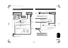
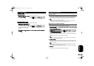
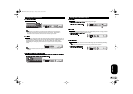
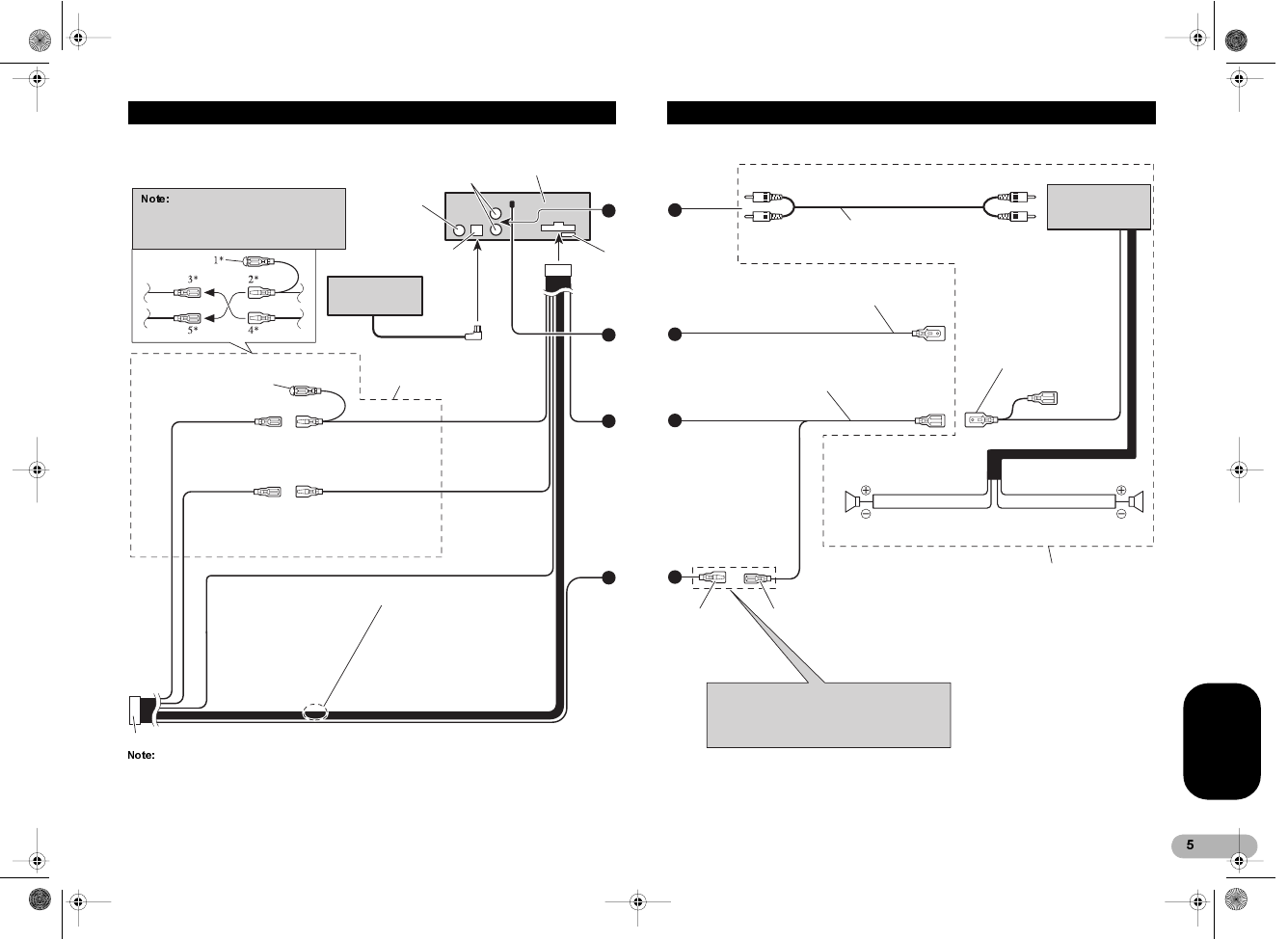
&RQQHFWLQJWKH8QLWV
A
B
C
D
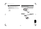
This product conforms to new cord colors.
Connect leads of the
same color to each other.
Depending on the kind of vehicle, the function
of 3* and 5* may be different. In this case, be
sure to connect 2* to 5* and 4* to 3*.
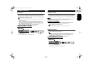
Cap (1*)
When not using this terminal,
do not remove the cap.
Red (4*)
To electric terminal controlled
by ignition switch (12 V DC)
ON/OFF.
Yellow (2*)
To terminal always supplied
with power regardless of
ignition switch position.
Red (5*)
Accessory
(or back-up)
Yellow (3*)
Back-up
(or accessory)
Black (ground)
To vehicle (metal) body.
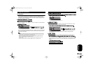
ISO connector
In some vehicles, the ISO connector may be
divided into two. In this case, be sure to connect
to both connectors.
This product
Antenna jack
Rear output
Fuse
IP-BUS cable
Multi-CD player
(sold separately)
IP-BUS input (Blue)
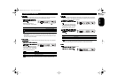
Speaker leads
White : Front left +
White/black : Front left -
Gray : Front right +
Gray/black : Front right -
Green : Rear left +
Green/black : Rear left -
Violet : Rear right +
Violet/black : Rear right -
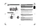
A
B
C
D
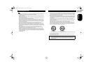
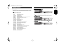
The pin position of the ISO connector will differ
depends on the type of vehicle. Connect 6* and 7*
when Pin 5 is an antenna control type. In another type
of vehicle, never connect 6* and 7*.
Blue/white
To system control terminal of the
power amp (Max. 300 mA 12 V DC).
Blue/white (7*)
To Auto-antenna relay control terminal (max. 300 mA 12 V DC).
Blue/white (6*)
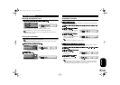
Power amp
(sold separateley)
Perform these connections when using a
different amp (sold separately).
Rear speaker (Left)
System remote control
Connecting cords with RCA pin plugs
(sold separately)
Rear speaker (Right)
Yellow/black
If you use a cellular telephone, connect it via the Audio
Mute lead on the cellular telephone. If not, keep the Audio
Mute lead free of any connections.
MAN-KEH-P5010R-GB_B.fm Page 5 Friday, October 6, 2000 2:22 PM