


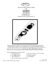
7
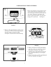
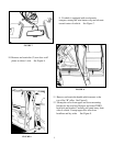
19. Install and route all video and audio cables, and any other added component requirements to their
respective places in the vehicle. Refer to component installation instructions for wiring diagrams. The
suggested routing of the video system cable is as follows: Above the headliner from rear A/C switch
opening to B-pillar. Down the B-pillar to the floor. Route the power lead to an accessory controlled
source. Connect the ground lead to the vehicle chassis. Route the remaining wiring (RCA plugs,
Remote Sensor extension, etc.) to the VCP location. See Figure 12. Connect per instructions included
with the video system. If video system if to be used as a television, install an appropriate antenna per
instructions included with the antenna.
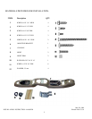
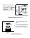
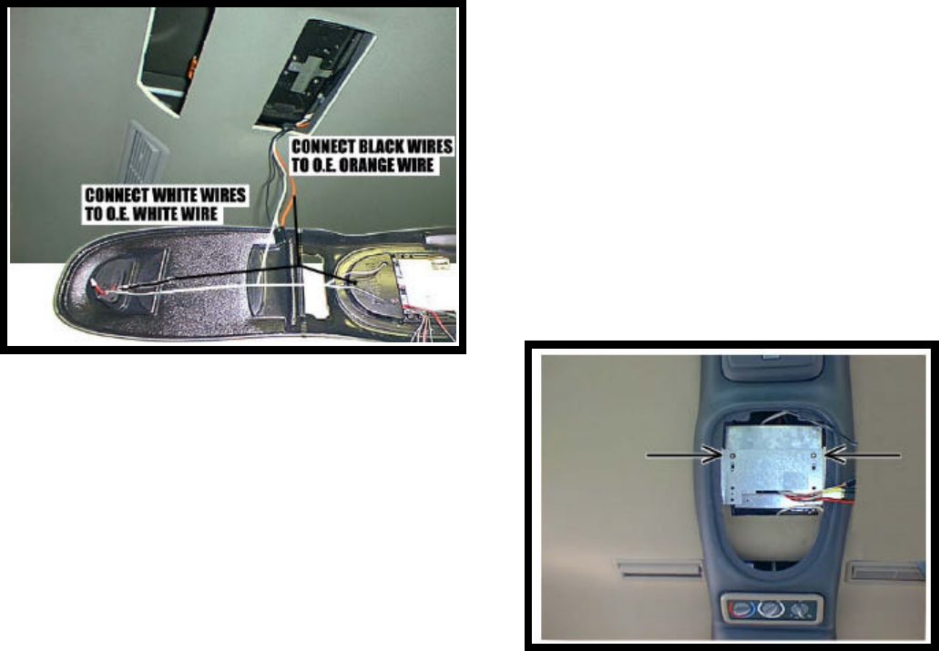
20. Construct a jumper harness that will connect the vehicle’s dome light wires to the lights in the console
and video system. Connect the white wires from lights to the O.E. white wire. Connect the black wires
from lights to the O.E. orange wires. Do not use O.E. black wire. See Figure 13.
Caution: Do not overtighten screws. Use
extra support for the console until
secured to the vehicle. Failure to do
so may cause damage to console or
installed components.
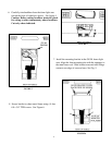
21. Raise console into approximate position and
connect wiring to O.E. components.
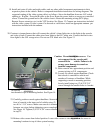
22. Loosely fit console against headliner. Check
that console is centered in vehicle and
matches all contours of headliner. While
supporting console in mounting position,
loosely install using two (2) 6-
32 X 3/4"
screws through the smaller holes in bracket
on console
into threaded clips on mounting bracket. See Figure 14.
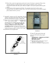
23. Carefully position console against headliner. Secure the
front of console to the inner roof of vehicle using (2)
two # 8 x 1 1/4" screws. Make sure console is centered
between sun visors before tightening screws completely.
See Figure 16. Tighten (2) 6-32 X 3/4" screws installed
in step 22.
24. Release video screen from locked position. Lower video screen to viewing position for access to
mounting locations in top of video system housing.
FIGURE
13
FIGURE
12
FIGURE
14