


9
10
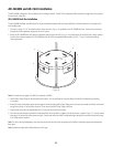
Support and Wire the Loudspeaker System
Important: Loudspeakers can potentially generate substantial vibration. In addition to ensuring all hardware is properly installed and secure,
you must use the Seismic Support Bracket on the loudspeaker to secure the loudspeaker to an appropriate structural support. This minimizes
the chance of the loudspeaker falling from the ceiling in the event the primary mount fails. Any cable or wire used as a secondary support
line must be strong enough to support ten times the weight of the loudspeaker system. Do not use rope, string, twine or other textile-based
line in the Seismic Support system as it is easily cut or burned. The Seismic Support attachment point and any fasteners used on the building’s
structure must also be strong enough to support ten times the weight of the loudspeaker.
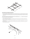
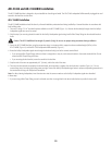
1. Using an appropriate fastener, attach the seismic support cable to a structural support of the building such as a beam.
2. Attach the loose end of the cable to the Seismic Support bracket on the loudspeaker system so that it is supported slightly below the ceiling. (This
should allow enough room to install the loudspeaker wiring as described in the following steps.)
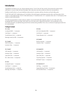
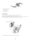
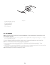
3. Use a #1 Phillips head screwdriver to loosen the Pivoting Connection Cover Retaining Screw (Figure 1), item c and swing the cover open.
4. Install a Wire Clamp Fitting into the cover plate hole (Figure 1), item d.
5. Feed the facility’s loudspeaker signal wiring through the cover plate hole with Wire Clamp Fitting making sure there is enough wire to strip, tin, and
install the connector. Do not secure the Wire Clamp Fitting at this time.
6. Strip the ends of the wires to approximately 0.4" (10 mm). Tin the ends of the wires.
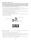
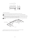
7. Locate the two Euro-style connector plugs included with the loudspeaker system (typically installed in the header (socket) connectors) (Figure 1),
item b and loosen the M3 wire retaining screws.
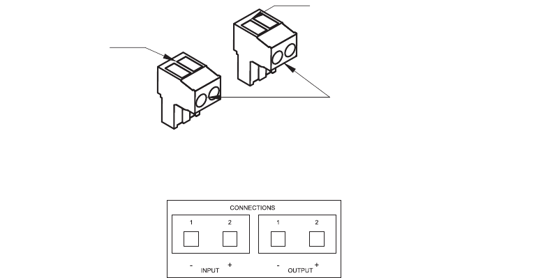
Note: Only one connector is required for signal input, the other is a signal output used for daisy-chaining loudspeakers. The polarity of each is marked
on the back can as shown in (Figure 15).
8. Insert each wire into its proper connector position (observe polarity) and tighten the M3 retaining screws.
9. Plug the two 2-pin Euro-style connector plugs into the single four-pin header connector.
10. Adjust the wiring at the entry point to provide for stress relief and closing the cover plate. Properly secure the Wire Clamp Fitting. (The Wire Clamp
Fitting prevents wire stress and strain from pulling the connections/connectors loose and prevents wear on the wires against the cover plate.)
11. Rotate the connection cover plate closed, making sure not to stress the connections or pinch the wires.
12. Tighten the Pivoting Connection Cover Retaining Screw. Make sure this screw is tight; if not it may rattle when the loudspeaker system is in use.
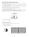
13. Follow the instructions on page 13 titled Mount the AD-C820 or AD-C821 Loudspeaker System.
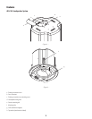
Four M3 retaining screws
Insert daisy chain wires 2 places
Insert wires 2 places
– Figure 14 –
– Figure 15 –
Note: It is not necessary to fully remove the screws.