


12
EN EN
TD-000367-00-A
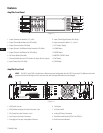
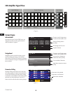
Outputs
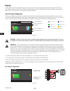
The CXD amplifiers have four configurable outputs. You can set the power, combine outputs (bridged and parallel), and adjust the DSP for each
output. When the output configuration of the amplifier changes, the output terminals, controlled by relays, change accordingly. Use the diagrams
shown in Figure 15 thru Figure 23 as a reference for wiring the loudspeakers.
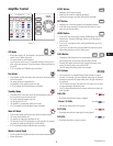
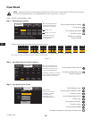
Select the Output Configuration
The first step in configuring your amplifier is to select a Preset based on the loudspeakers being connected to the amplifier. You can use a factory
preset, and then adjust the parameters as needed, then save the configuration as a user-defined preset. In addition, you can use the "Preset Wizard"
on page 16 to create presets from the ground up. When the configuration is changed, all four channels are automatically muted.
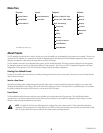
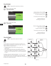
— Figure 14 —
F1: A B C D
F7: ABC D
M
ABC
M
D
Input number
Sub-woofer
Mid-Frequency
Full Range
High-Frequency
Low-Frequency
Current Configuration
Selected Configuration
Input Mixer
Output Configuration
Frequency Range color
Frequency Range Color Codes
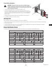
WARNING!:
When the AC Power is on, there is a potential of having dangerous voltage at the output terminals on the rear of
the amplifier. Use caution not to touch these contacts. Turn off the AC Mains disconnect switch prior to making any connections.
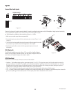
IMPORTANT:
QSC recommends that you connect jumpers between the output terminals where the terminals are the same points
electrically. When configuring your amplifier, there are going to be some loudspeaker connections that are noted as being "electrically
the same point". In Figure 15, all four channels are in parallel with the "electrically the same" terminals jumpered as recommended. In
addition, you can connect one loudspeaker to each of the four output channel terminals, and the four loudspeakers are in parallel; in this
case you would not need to jumper the terminals. You can connect four loudspeakers to one channel's output terminals (i.e. T1 and T2),
and the four loudspeakers are in parallel; in this case you would want to jumper the terminals. In all of the examples below, the
"electrically the same" terminals are shown with jumpers installed.
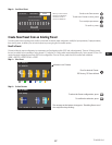
1. Turn the AC Mains power switch on the back of the amplifier to on. The amplifier starts in the Run mode.
2. Press and release the front-panel power button. The button flashes red, the amplifier is in Mute All mode.
3. Select the configuration appropriate for your loudspeakers, using either Preset Recall, or the Preset Wizard.
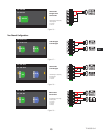
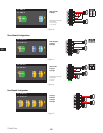
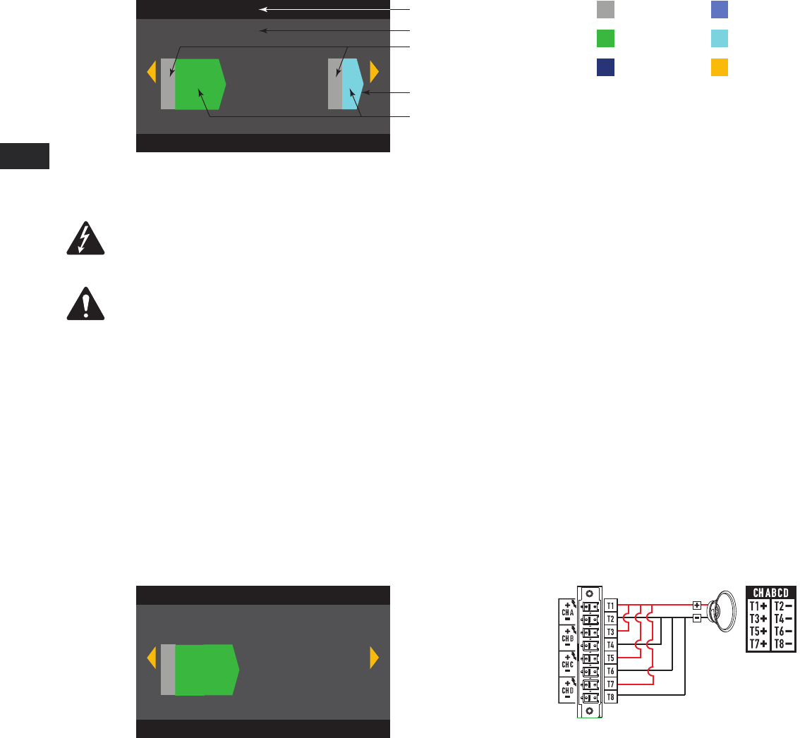
The following is a list of configurations for 1, 2, 3, and 4-channel outputs. This is not an exhaustive list, but is intended to give you an idea of what is
available and how the outputs would be wired.
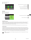
One-Channel Configurations
— Figure 15 —
F9: ABCD
F9: ABCD
ABCD Parallel
M
ABCD
The following are electrically
the same point
T1+, T3+, T5+, and T7+
T2-, T4-, T6-, and T8-