


6
EN EN
TD-000367-00-A
Features
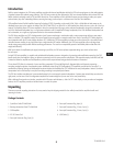
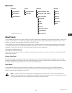
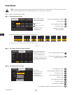
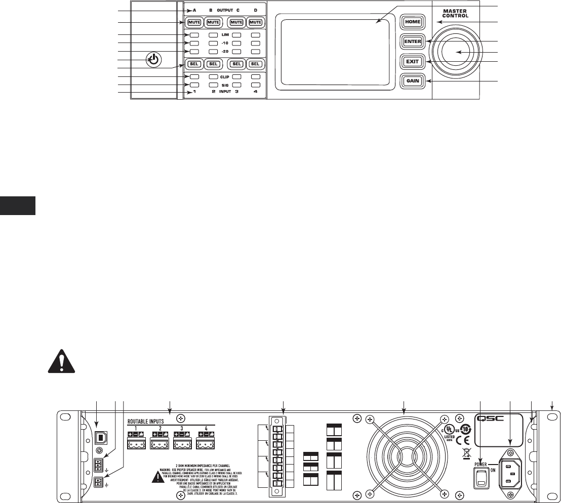
Amplifier Front Panel
— Figure 1 —
1
2
3
4
5
6
7
8
12
13
14
15
16
9
10
11
1. Output channels are labeled A, B, C, and D
2. Output Channel Mute Buttons and LEDs (Red)
3. Output Channel Limiter LEDs (Red)
4. Output Channel -10 dB Below Limiter Activation LEDs (Blue)
5. Output Channel -20 dB Below Clip LEDs (Blue)
6. Soft Power Button (Blue/Red)
7. Channel Select Buttons and LEDs (Amber for Input, Blue for Output)
8. Input Channel Clip LEDs (Red)
9. Input Channel Signal-Present LEDs (Blue)
10. Input channels are labeled 1, 2, 3, and 4
11. LCD Graphic Display
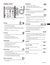
12. HOME Button
13. ENTER Button
14. MASTER CONTROL Knob
15. EXIT Button
16. GAIN Button
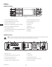
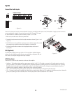
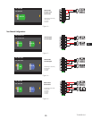
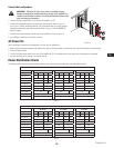
Amplifier Rear Panel
NOTE:
The CXD4.3, and CXD4.5 models have a different rear panel configuration than the CXD4.2 rear panel. The difference is that the
position of the fan and the eight-pin Euro-style connector and associated information are interchanged.
— Figure 2 —
CH AB
T1
+
T3
+
T2
-
T4
-
CH CD
T5
+
T7
+
T6
-
T8
-
CH ABC
T1
+
T3
+
T5
+
T2
-
T4
-
T6
-
CH ABCD
T1
+
T3
+
T5
+
T7
+
T2
-
T4
-
T6
-
T8
-
CH AB
+
CD
T1
+
T3
+
T5
-
T7
-
CH C
+
D
T5
+
T7
-
CH A
+
B
T1
+
T3
-
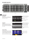
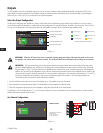
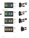
BRIDGED
OUTPUTS TO SPEAKERS
CH A
CH D
CH C
CH B
+
+
+
+
-
-
-
-
T1
T4
T3
T2
T5
T8
T7
T6
SETTINGS CAN BE
CONFIGURED FOR
70V, 100V AND
200V DIRECT
OUTPUT.
PARALLEL CHANNEL
COMBINING APPLICATIONS
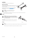
THIS PRODUCT SHOULD BE SUPPORTED ON ALL
FOUR CORNERS WHEN INSTALLED IN A RACK
USB
HEARTBEAT
GPO
GPI
1 4 5 6 7 8 102 93
1. USB Type B, four-pin
2. GPO/Heartbeat (output) Euro-style Connector, 3-pin
3. GPI (input) Euro-style Connector, 2-pin
4. Four three-pin Euro-style Connectors
5. One eight-pin Euro-style Loudspeaker Connector
6. Cooling fan
7. AC Power Switch
8. Locking IEC Power Connection
9. Rear Rack-mount Bracket (CXD4.3 and CXD4.5)
10. Front Rack-mount Brackets