


AF1 • 7
MISCELLANEOUS PARTS
1 2.5mm power jack (J4)
2 PC mount RCA jacks (J1, 3)
3 DPDT pushbutton switch (S1, 2, 3)
1 1/4” stereo headphone jack (J2)
1 AF1 printed circuit board
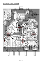
RAMSEY Learn-As-You-Build KIT ASSEMBLY
There are numerous solder connections on the AF1 printed circuit board.
Therefore, PLEASE take us seriously when we say that good soldering is
essential to the proper operation of your transmitter!
• Use a 25-watt soldering pencil with a clean, sharp tip.
• Use only rosin-core solder intended for electronics use.
• Use bright lighting, a magnifying lamp or bench-style magnifier may
be helpful.
• Do your work in stages, taking breaks to check your work. Carefully
brush away wire cuttings so they don't lodge between solder
connections.
We have a two-fold "strategy" for the order of the following kit assembly
steps. First, we install parts in physical relationship to each other, so there's
minimal chance of inserting wires into wrong holes. Second, whenever
possible, we install in an order that fits our "Learn-As-You Build" Kit building
philosophy. This entails describing the circuit that you are building, instead of
just blindly installing components. We hope that this will not only make
assembly of our kits easier, but help you to understand the circuit you’re
constructing.
For each part, our word "Install" always means these steps:
1. Pick the correct part value to start with.
2. Insert it into the correct PC board location.
3. Orient it correctly, follow the PC board drawing and the written
directions for all parts - especially when there's a right way
and a wrong way to solder it in. (Diode bands, electrolytic
capacitor polarity, transistor shapes, dotted or notched ends
of IC's, and so forth.)
4. Solder all connections unless directed otherwise. Use enough
heat and solder flow for clean, shiny, completed connections.