


AF1 • 8
Now, let's get building!
Since you may appreciate some “warm-up” soldering practice as well as a
chance to put some “landmarks” on the PC board, we’ll first install some
“hardware” components. This will also help us to get acquainted with the up -
down, left - right orientation of the circuit board. Remember that the
components will be mounted on the “component” side of the circuit board
and soldered on the “solder” side of the circuit board.
1. Identify and install DPDT switch S3. Be sure to push the switch flat to
the circuit board. Solder all six connections.
2. In the same manner install DPDT toggle switches S1 and S2. Once
again, be sure to push the component flush to the circuit board before
soldering.
3. Install R14, the PC mount 10K ohm potentiometer. Solder all the
connections for secure, trouble free adjustment.
4. Install R13, the 100K ohm PC mount potentiometer.
5. Moving to the rear of the circuit board, install J1 and J3, the PC mount
RCA type. Solder all four connections securely.
6. Inspect the 1/4” headphone jack. Notice the seven pins protruding
from the bottom of the component. Be sure that none of these
connecting pins have been bent over before installing J2. Solder all
connections.
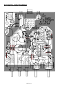
Next we’ll begin our “learn as you build” with the power supply section of the
circuit. Pay particular attention to the placement of the polarized components
as they can overheat (and even explode) if installed incorrectly.
7. Install J4, the 2.5 mm power jack.
8. Install C17, .01 uF disc capacitor [marked .01 or 103 or 10nF].
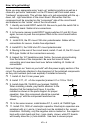
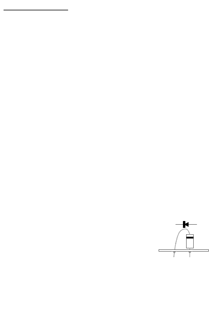
9. Install diode D8, 1N4002 type [marked 1N4002].
When installing a diode, pay careful attention to the
direction that the banded end faces. It must be
installed as shown in the parts diagram for proper
operation. Also, this component should be mounted
“standing up” with the component leads bent as
shown.
10. In the same manner, install diodes D7, 3, and 6, all 1N4002 type.
11. Install C18, 1000 uF electrolytic capacitor. Electrolytic capacitors are
polarized with a (+) and a (-) lead and must be installed in the correct
orientation. Ordinarily, only the negative side is marked on the capacitor
body with a dark band and the (-) sign clearly shown, while PC boards
will usually show the (+) hole location. Use care to ensure proper