


AF1 • 9
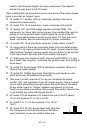
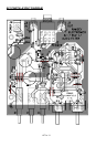
polarity. See the parts diagram for proper placement. The capacitor
should fit snugly down to the PC board.
When installing the components be sure to save some of the longer clipped
leads to use later as “jumper” wires.
12. Install C11, another 1000 uF electrolytic capacitor. Be sure to
observe the proper polarity.
13. Install C19, 10 uF electrolytic. Again, remember that polarity!
14. Identify VR1, the 7808 voltage regulator [marked 7808]. This
component, too, has a right and wrong way to be installed. Be sure the
writing on the component faces inward toward the center of the PC
board. Using gentle pressure push the part about 1/4” from the circuit
board, and solder. See the parts diagram for proper installation.
15. Install C20, 10 uF electrolytic capacitor. Is that polarity correct?!
16. Using some of the scrap component leads, form and install jumper
wire JMP1 in the holes provided in the PC board. Jumper wires act like
little electronic “bridges” carrying signals from the bottom to the top side
of the circuit board, and then back to the bottom side again.
17. Grab some more scraps of leads, form and install JMP2, 3, 4. Hey,
this is better than recycling - if we keep this up there won’t be anything to
throw away!
18. Install C9, the last large 1000 uF electrolytic capacitor. Be sure to
observe the proper polarity.
19. Install D5, 1N4002 type diode. Note that the part stands up, and,
watch which way the banded end is pointed.
That wasn’t so bad, now was it! You’ve just completed the bridge
rectifier, filter, and regulation of your AF1 power supply. Take a moment
now to check parts placement and inspect the solder side of the board
for any solder opens or “bridges” between components or foil runs.
Touch up any solder connections that are less than perfect. Now its time
to get building the audio path through the AF1.
20. Install C16 (its adjacent to J3 towards the rear of the PC board),
.01 uF disc [marked .01 or 103 or 10nF].
21. Install C15, .01 uF disc [marked .01 or 103 or
10nF].
22. Install R19, 1K ohm [brown-black-red]. Note that
this component is mounted standing up. Resistors
aren’t polarized, so you can install it either way.