


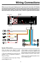

• Disconnect negative battery terminal before starting installation. Consult the vehi-
cle’s owner’s manual for proper instruction.
• The unit is designed for a 12Volt DC negative ground operation system only. Before
installing the unit, confirm that your vehicle is a 12Volt DC negative ground system.
• Be sure to connect the color coded leads according to the diagram. Incorrect con-
nections may cause the unit to malfunction or damage the vehicle’s electrical sys-
tem.
• Be sure to connect the negative (-) speaker leads to the negative (-) speaker termi-
nal. Never connect negative (-) speaker leads to chassis ground.
• The unit is only designed for use with 4 speakers. Do not combine output for use
with 2 speakers. Do not ground negative speaker leads to the chassis ground.
• Make sure all the connections are completely correct before turning on your unit.
• When replacing the fuse(s), the replacement must be of the same amperage as
shown on the fuse holder.
• Do not block vents or heater panels. Blocking them will cause heat to build up in-
side and may result in fire.
• After completing the installation and before operating the unit, reconnect the bat-
tery. Then press the (RES) button with a pointed object, such as a ball-point pen to
set the unit to its initial status.
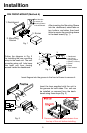
Notes On Installation
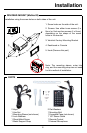
Tools For Installation
• The 2 removal keys are supplied for removing the old unit and replacing with the
“VR500CS-BT”.
The following tools and supplies may also be needed for the installation:
TOOLS
• Phillips Screw-drivers
• Wire Stripper
• Wire Cutter
• Hammer
• Pencil
• Electrical Tape
• Electric Drill
SUPPLIES
• Machine Screws
• Crimp Connectors
• 14 Gauge Wire for Power Connections
• 14-16 Gauge Speaker Wires
The above are NOT INCLUDED with the VR500CS-BT and must be purchased seperately.
3