


ADJUSTMENT PROCEDURES
_ _
13
1.Adjustment Conditions
Power supply voltage DC
9.0 V.
Input the suitable signal for each adjustment.
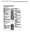
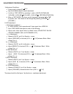
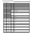
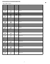
It shifts to TEST MODE by pressing in order of [OUT] [OUT][IN] [IN]
[VOLUME-] [VOLUME [RETURN] [POSITION].
When in TEST MODE, the items can be changed by pressing
or
of joystick, and the values can be changed by pressing [VOLUME ] or
.
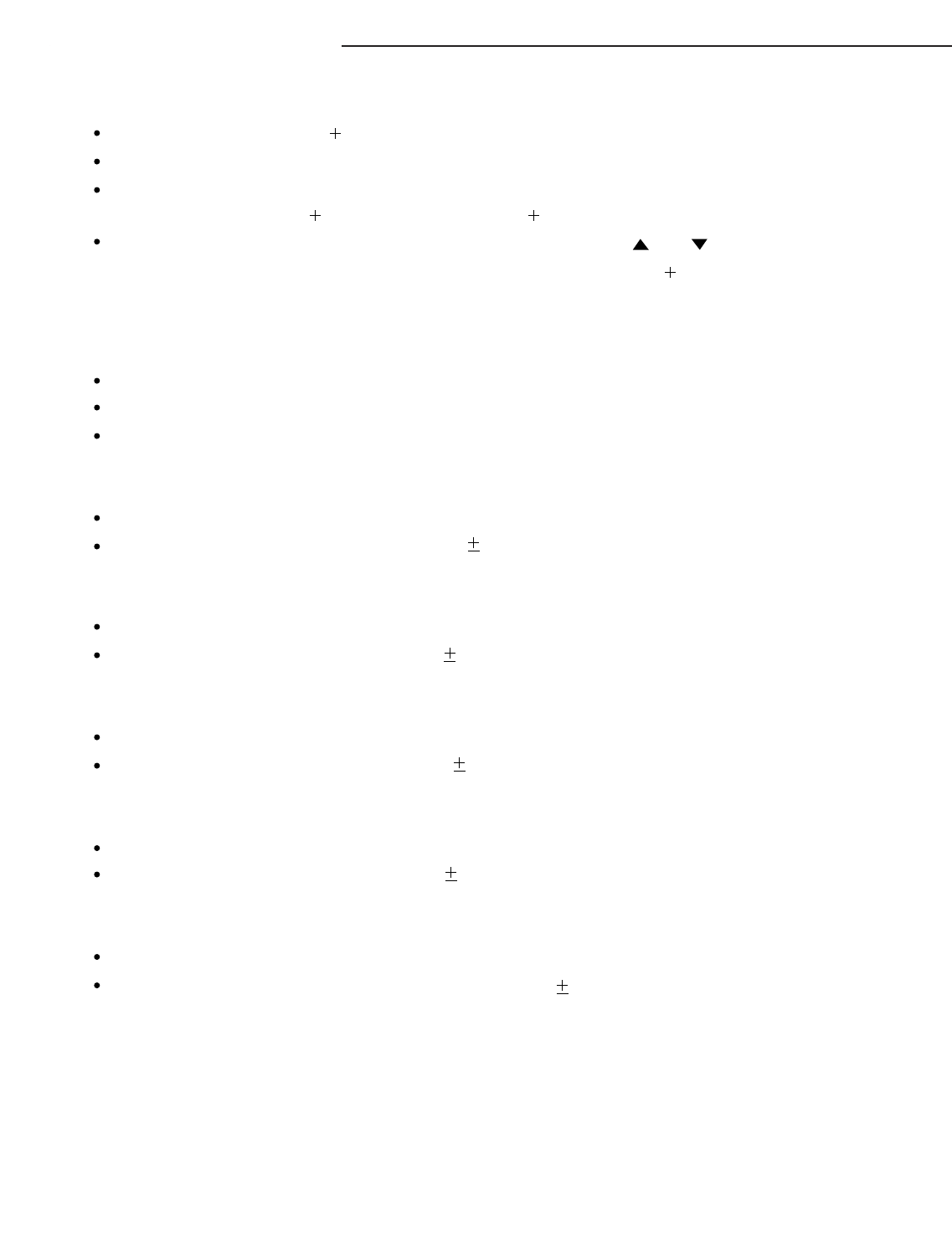
2.LCD Adjustment
< Adjustment conditions >
In VIDEO MODE, input monochrome10 step signal from VIDEO IN.
Go to TEST MODE and adjust in order of the following.
Adjust each video signal value by default value (COLOR/TINT/ BLACK:
CENTER, DIMMER: MAX, AUTO DIMMER: OFF ).
1 )
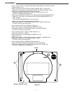
B- B Adjustment
Observe VG(CS1, pin 8 ) by Synchro - scope.
Adjust [RGB AMP] to become [4.0V P- P 0.1V] between Black - Black
voltage (V
B-B )
2) B - W Adjustment
Observe VG(CS1, pin 8 ) by Synchro - scope.
Adjust [BRIGHT] to become [2.9V
P- P 0.1V] between Black - White
voltage (V B- W ).
3) Red Adjustment
Observe VR(CS1, pin 7 ) by Synchro - scope.
Adjust [SUB R] to become [2.9V P- P 0.1V] between Black - White
voltage (V B- W ).
4) Blue Adjustment
Observe VB(CS1, pin 6 ) by Synchro - scope.
Adjust [SUB B] to become [2.9V
P- P 0.1V] between Black - White
voltage (V B- W )
5) VCOM Adjustment
Observe VCOM(CS1, pin 9 ) by Synchro - scope.
Adjust [COM AMP] to become wave Form [4.0V P- P 0.1V]
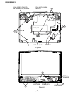
The steps should be like figure 1 by the above - mentioned adjustment.
]
[VOLUME-] [VOLUME
]
[ ]
[ ]
[VOLUME-]