


EXPLANATION OF CIRCUIT
_ _
30
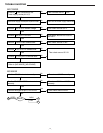
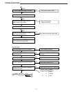
1.NAVI BLOCK
In NAVI MODE, the power supply is supplied to NAVI BLOCK and SERVO PCB.
The NAVI signal from the microcomputer is Hi, and 3.3V and 5V are supplied to
NAVI BLOCK from Q168 and 108.
5V is supplied to SERVO PCB from Q120.
a. CPU(IC801)
IC801 controls ASIC, MEMORY, and GRAPHIC CONTROLER etc. in MAIN CPU.
Taking in the key signal from GPS data and microcomputer are also performed
by CPU.
And CPU detects the state of BEEP output, Parking brake, and Disc cover etc.
b. ASIC(IC861)
ASIC performs output of the control signal at the time of memory access of CPU,
and communicates with DVD drive.
Voice guidance is outputted through IC881(DAC)and IC82(LPF/AMP)by ASIC.
c. MEMORY(IC841,842,843)
IC841 and 842 are used for memory of Map data and calculation of NAVI
microcomputer by SDRAM.
IC843 is used for memory of program software, font data, bit map data, and
back up data of course and initial setting by FLASH.
d. GRAPHIC CONTROLER(IC901)
The data sent from NAVI microcomputer or MEMORY is changed into the data for
display.
IC931 is used as work memory by DRAM.
Graphic data is inputted by 6- bit RGB data synchronizing with DCLK.
IC 941 is inputted to pin 3 and pin14 by PLL.
15.7KHz is compared and DCLK is outputted from pin 4.
e. VIDEO DAC(IC951)
Digital RGB outputted from IC901 is synchronizes with DCLK and changed into
ANALOG, and RGB signal and Composite video signal are outputted.
f. GPS
GPS tuner and MAIN PCB are connected by CS971 and wire.
Pin 8 is power supply for tuner, pin 9 is power supply for antenna, and pin 2 is
power supply for backup.
Pin 6 receives data from NAVI microcomputer, and data is transmitted to NAVI
Microcomputer from pin 7.
From GPS tuner, position/time data is outputted for every seconds, and it is
inputted into pin 145 of NAVI microcomputer.