7
DSR Series
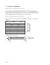
External view
1
2
3
4
5
6
7
8
9
T R
+
_
B
A
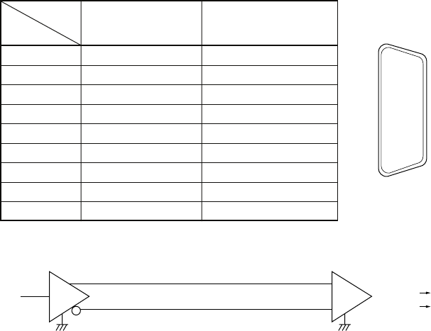
T : Transmit R : Receive
A < B “1” (MARK)
A > B “0” (SPACE)
Signal
Controller Device
Pin
1 Frame Ground Frame Ground
2 Receive A Transmit A
3 Transmit B Receive B
4 Transmit Common Receive Common
5 Spare Spare
6 Receive Common Transmit Common
7 Receive B Transmit B
8 Transmit A Receive A
9 Frame Ground Frame Ground
4. Connector Pin Assignment
Interface connector : 9 pin D-subminiature female (D-9S)
The pin assignment for the CONTROLLER and the DEVICE is as shown in the following table.
Among the DSR series VTRs, the VTRs (DSR-85/85P) that have the built-in CONTROLLER function,
obtain the following CONTROLLER pin assignment when they execute the QSDI dubbing and also
when the RECORDER lamp or the PLAYER lamp turns on the control panel.
Except for that, it’s become pin assignment of DEVICE.
The VTR not had the function as CONTROLLER (DSR-60/60P) is always become pin assignment of
DEVICE.
A and B are defined as shown below.


