1
DSR Series
START
BIT
D0
(LSB)
D1 D2 D3 D4 D5 D6 D7
(MSB)
PARITY STOP
BIT
(MARK)
(SPACE)
1. Summary
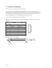
The DSR series VTR, Remote Control Connector Panel, incorporate with a 9-pin D-Subminiature
connectors for REMOTE.
This connector is utilized for a serial control system.
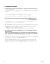
The definition of CONTROLLER and DEVICE is shown in the follows,
“CONTROLLER” means the unit which controls VTR.
“DEVICE” means the unit (VTR) which is controlled.
Example 1)
When the DSR series VTR is connected by REMOTE (9-pin) connector, the VTR as the recorder
means CONTROLLER and the VTR as the player means DEVICE.
Example 2)
When the editing controller is connected with one or plural DSR series VTR (s), this editing control-
ler is CONTROLLER and all VTRs are DEVICEs.
2. Interface System Overview
. Conforming to EIA RS-422A.
. Full duplex communications channel is utilized.
. Data is transmitted asynchronously, bit serial, word serial with data exchange between devices.
. Standard transmission rate on the interface bus is 38.4 kilobits per second (kb/s).
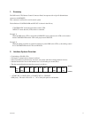
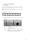
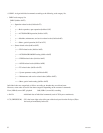
. The data word utilized by the interface system is as follows :
. 1 START BIT + 8 DATA BITs + 1 PARITY BIT + 1 STOP BIT.
ODD parity : The total of D0 + D1 +..... D7 + Parity bit equals an odd number.


