Chapter 8: Installation verification
66 Installing and Configuring the Avaya S8400 Media Server February 2006
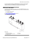
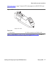
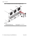
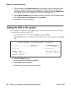
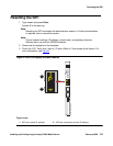
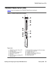
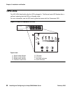
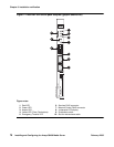
Faceplate interfaces
The TN8400AP Media Server maintenance complex has the following faceplate interfaces as
shown in Figure 5:
TN8400AP Media Server faceplate on page 65:
● TN8400 Circuit Pack Failure LED - This solid red LED is lit when there is a detected
TN8400AP Media Server circuit pack failure.
-
Solid red during a turn on sequence and during a reset. When turn on or reset is
complete and there are no failures, the LED turns off.
-
Solid red indicates that there is a failure on the TN8400AP Media Server circuit pack.
● Shutdown button - Hold in the shutdown button for 2 seconds to start a shutdown. The
Communication Manager Processor Complex remains in a shutdown state until power is
removed and then reapplied. This switch gracefully turns off the operating system and file
system so as to not destroy data and require a disk recovery process.
● OK to Remove circuit pack LED - This green LED provides a visual status of the shutdown
process.
-
LED off indicates the system is operational.
-
Flashing indicates that the shutdown is in progress.
-
Solid indicates It is safe to remove the TN8400AP Media Server circuit pack from the
carrier or turn off the carrier where the TN8400AP Media Server circuit pack resides.
● Major Alarm Status LED - This red LED indicates that a major alarm condition is detected.
● Services Ethernet Link Status LED - This green LED shows the status of the Services
Ethernet link. The LED is on when the link is up. The LED flashes any time data transitions
are detected.
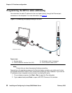
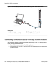
● Services RJ45 connection to the Services laptop - This Ethernet port provides access to a
single 10/100 BaseT Ethernet interface by an RJ-45 connector. This port is connected to
the Services laptop, and is used for on-site Services access to the system.
● Compact Flash in Use LED - This yellow LED indicates that the Compact Flash memory is
being accessed.
● Compact Flash slot - This slot provides access for storage of translations and selection
application data.
● USB port for the USB CD-ROM drive - Used to communicate with peripheral equipment
such as a USB CD/DVD ROM for software/firmware updates. Do not connect the modem
to this port.
● Server Active LED - This green LED:
-
The LED is on when the Maintenance Processor detects that the primary application of
the Communication Manager Processor is loaded and running.
-
The LED is off during a power-on reset or when the system is shutting down.
-
The LED flashes when a diagnostic /self test is running.