Commander GP User Guide
Issue code: gpxu2
2-16 Getting Started
Torque-producing current limit
Set parameter 0.06 Current limit at the required
percentage of rated motor torque (or rated active
torque-producing current).
The current limit is used to protect the motor and
Drive from excessive current and applies under
motoring and regenerating conditions. When the
Drive is operating in torque control, the current
limit limits the value of torque demand.
The total motor current comprises a magnetizing
current and an active (torque-producing) current.
Since the maximum torque produced by the motor
is proportional to the value of parameter 0.06
Current limit, this current limit is a torque-producing
current limit.
When 0.06 is set at its maximum value, the
maximum total motor current is as follows:
150% x FLC
Where FLC is the rated (full-load) current of the
Drive.
The maximum value of 0.06 is given by the
following (but cannot exceed 400 (%)):
[. ]
( . ) ( cos )
cos [ . ]
(%)006
15 1
046
100
22
MAX
FLC
==
−−−−
××××
φφ
φφ
Where:
[0.46] = Value of Motor – rated current
cosφ is the power factor of the motor.
Note
The results from these equations may not
correspond exactly with the maximum
output current from the Drive, since the
Drive may round up the calculated figure.
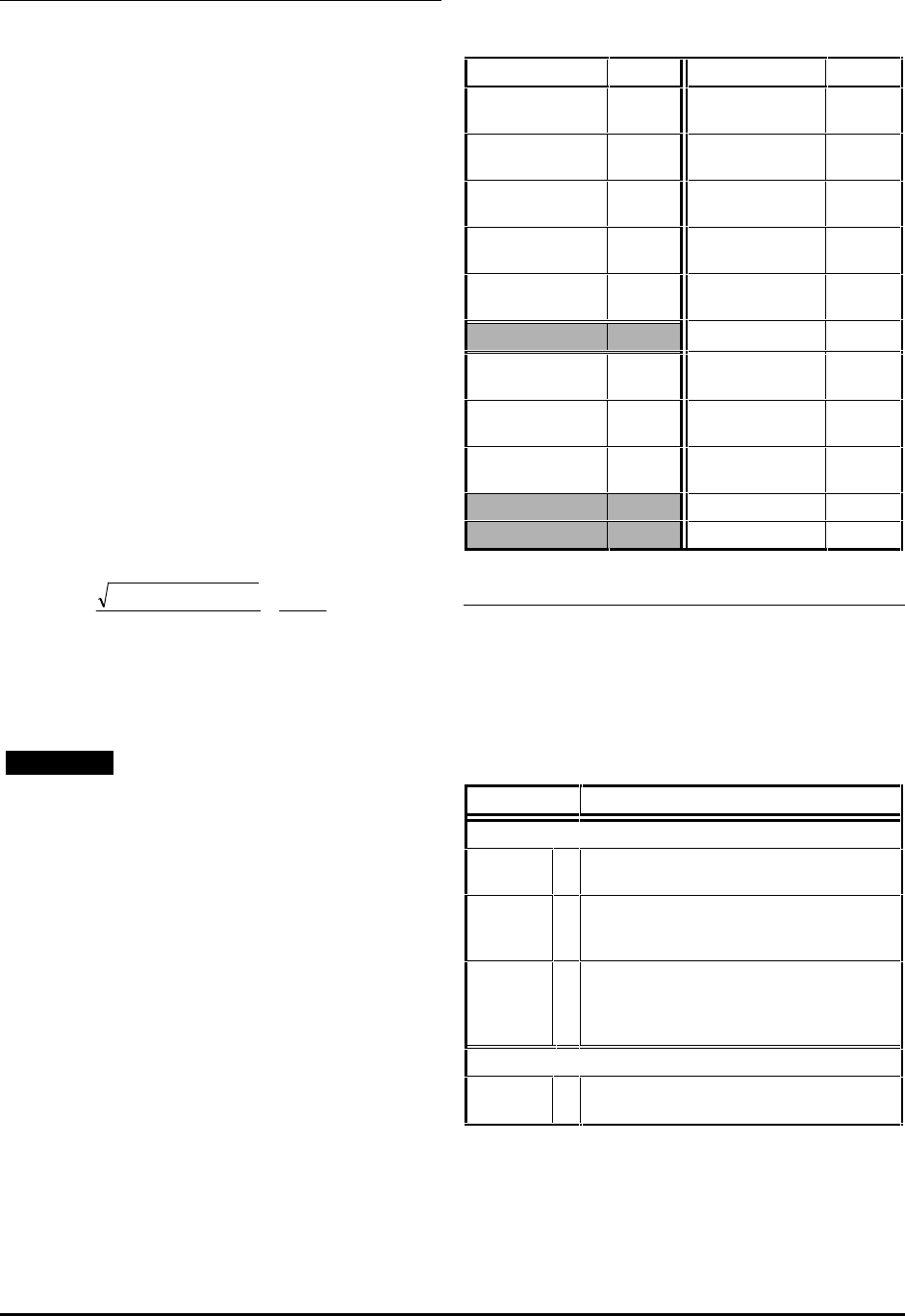
The value of FLC is given in the following table.
Values of FLC
Model FLC (A)
FLC (A)
GPD 1201
GPD 1401
2.1
34
GPD 1202
GPD 1402
2.8
40
GPD 1203
GPD 1403
3.8
46
GPD 1204
GPD 1404
5.6
60
GPD 1205
GPD 1405
9.5
70
74
GPD 2201
GPD 2401
12
96
GPD 2202
GPD 2402
16
124
GPD 2203
GPD 2403
25
156
180
202
Voltage-control modes
The default setting is as follows:
Macro 1: Fd
Macros 0, 2, 3, 4, 5, 6, 7: Ur_I
To change the voltage control mode, select the
required setting in parameter 0.07 Voltage mode
selector, as follows:
Setting Function
Vector modes
Ur_S
0 Motor stator resistance is measured each
time the Drive is started.
Ur_I
1 Motor stator resistance is measured at
power-up if the
EXTERNAL TRIPEXTERNAL TRIP contact is
closed and no other trip condition exists.
Ur
2 Motor stator resistance is not measured
(use this mode only after having used
Ur_S or Ur_I to measure the stator
resistance).
Fixed boost mode
Fd
3 Fixed voltage boost that can be manually
adjusted by parameter 0.08 Boost voltage.
The Vector modes give better performance at low
speed than the fixed-boost mode, but require the
stator resistance to be accurately measured by the
Drive.


