22 Helix
GB
Servicing
9. Servicing
Before proceeding, follow the Pressure Relief
Procedure outlined previously in this manual.
Additionally, follow all other warnings to reduce the
risk of an injection injury, injury from moving parts
or electric shock. Always unplug the sprayer before
servicing!
i
All service instructions apply to both Component
A and Component B pumps, unless otherwise
specied. If ordering a new motor controller (Fig.
17, item 12), make sure to order it for the correct
Component Pump (see “Motor Assembly” in the
Spare Parts List section, page 32-33).
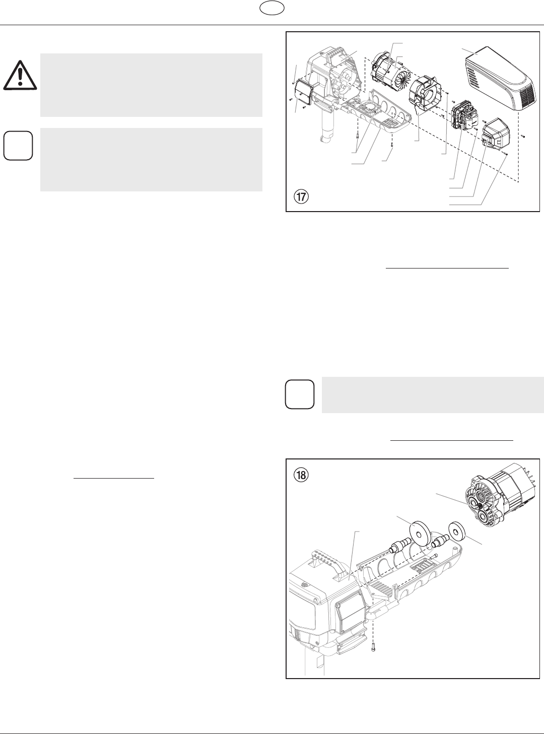
9.1 Replacing the Motor Assembly (Fig. 17)
1. Disconnect the power cord.
2. Loosen and remove the two motor shroud screws (1). Remove
the motor shroud (2).
3. Loosen and remove the three belly pan screws (3). Remove
the belly pan (4).
4. Loosen and remove the two motor cover screws (5). Remove
the motor cover (6).
5. Disconnect all wires between the motor and the sprayer.
6. Disconnect the wires between the motor (9) and the control
panel.
7. Loosen and remove the two motor controller screws (11).
Remove the motor controller (12).
8. Loosen and remove the four motor bae screws (13).
Remove the motor bae (14).
9. Loosen and remove the three motor mounting screws (15).
10. Pull the motor out (9) of the gearbox housing (16).
11. With the motor removed, inspect the gears in the gearbox
housing for damage or excessive wear. Replace the gears, if
necessary.
12. Install the new motor (9) into the gearbox housing.
13. Secure the motor with the three motor mounting (15) screws.
14. Reconnect the wires between the sprayer and the new motor
(refer to the Electrical Schematic, section 8.7).
15. Place the bae (14) over the end of the motor assembly (9).
Secure with the four motor bae screws (13).
16. Place motor controller (12) back into place behind the motor
bae (14). Secure with the two motor controller screws (11).
17. Reconnect all wires between the motor and sprayer.
18. Reconnect the wires between the motor and the control
panel.
19. Place the motor cover back over the motor controller. Secure
with the two (5) motor cover screws.
20. Put the belly pan (4) back in place and secure with the three
belly pan screws (3).
21. Slide the motor shroud (2) over the motor assembly (9).
22. Secure the motor shroud (2) with the two motor shroud
screws (1).
1
6
5
11
12
13
14
2
15
16
7
9
3
4
8
9.2 Replacing the Gears (Fig. 18)
1. Follow steps 1-10 in Replacing the Motor Assembly to
remove the motor and control panel.
2. Inspect the armature gear (1) on the end of the motor for
damage or excessive wear. If the gear is completely worn out,
replace the motor assembly.
3. Remove and inspect the 1st stage gear (2) and 2nd stage
gear (3) assemblies for damage or excessive wear. Replace, if
necessary.
4. Inspect the front gear box assembly (4) for damage or
excessive wear. If damaged or worn, replace the front gear
box assembly.
Clean and rell the gear box cavity up to the rear
face of each gear with Lubriplate (P/N 314-171).
5. Reinstall the motor into the gearbox housing.
6. Follow steps 11-22 in Replacing the Motor Assembly to
replace the motor and control panel.
1
3
2
4


