10 Helix
GB
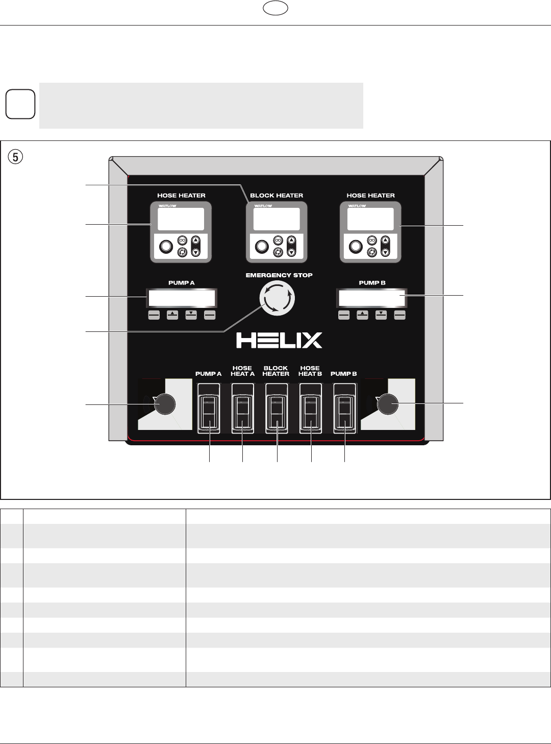
Control Panel
4. Control Panel
The control panel contains all of the system controls that allow the sprayer to function
properly, as well as being the main display panel that gives information about the system.
i
Items 1 - 5 below are duplicated - one for each pump. If they are located on
the left side of the panel, they serve the “A” side of the system. If they are
located on the right, they serve the “B” side. If it is located in the middle, it
serves the entire system.
MAX
PSI
MIN
PSI
Clean
MAX
PSI
MIN
PSI
Clean
MENU
1
SEL
4
2 3
MENU
1
SEL
4
2 3
MAX
PSI
MIN
PSI
MAX
PSI
MIN
PSI
1
EZ-ZONE
ºF
ºC
Z
O
N
E
8.8:8.8
8 8.8:8.8
EZ
1
EZ-ZONE
ºF
ºC
Z
O
N
E
8.8:8.8
8 8.8:8.8
EZ
1
EZ-ZONE
ºF
ºC
Z
O
N
E
8.8:8.8
8 8.8:8.8
EZ
854 45
1a
3a
7
6
2a
2b
3b
1b
1 Heated hose temperature control This panel regulates the spray material temperature for the applicable heated hose.
2 Control Displays Thedisplaysshowvariousmenuscreensthatallowtheusertocustomizeandmonitorpump
operation using the function keys (1 - 4).
a A-side independent controller When the component pumps are unlinked, this controls Component Pump A.
b Master controller / B-side independent
controller
When the component pumps are linked, the master controller controls both component
pumps. When the component pumps are unlinked, this controls Component Pump B only.
3 Component pump pressure control Adjusts the pump pressure of the applicable Component Pump.
4 ON/OFFswitch,ComponentPump ThisswitchturnstheapplicableComponentPumpONandOFF.
5 ON/OFFswitch,hoseheater ThisswitchturnstheapplicablehoseheaterONandOFF.
6 Block heater control This panel regulates the temperature of the heater block
7 Emergency Shuto Pushing this button will instantly shut down the system. However, pressing this button
WILL NOT depressurize the system. Follow the Pressure Relief Procedure.
8 ON/OFFswitch,blockheater ThisswitchturnstheblockheaterONandOFF


