English English
© Titan Tool Inc. All rights reserved. 11
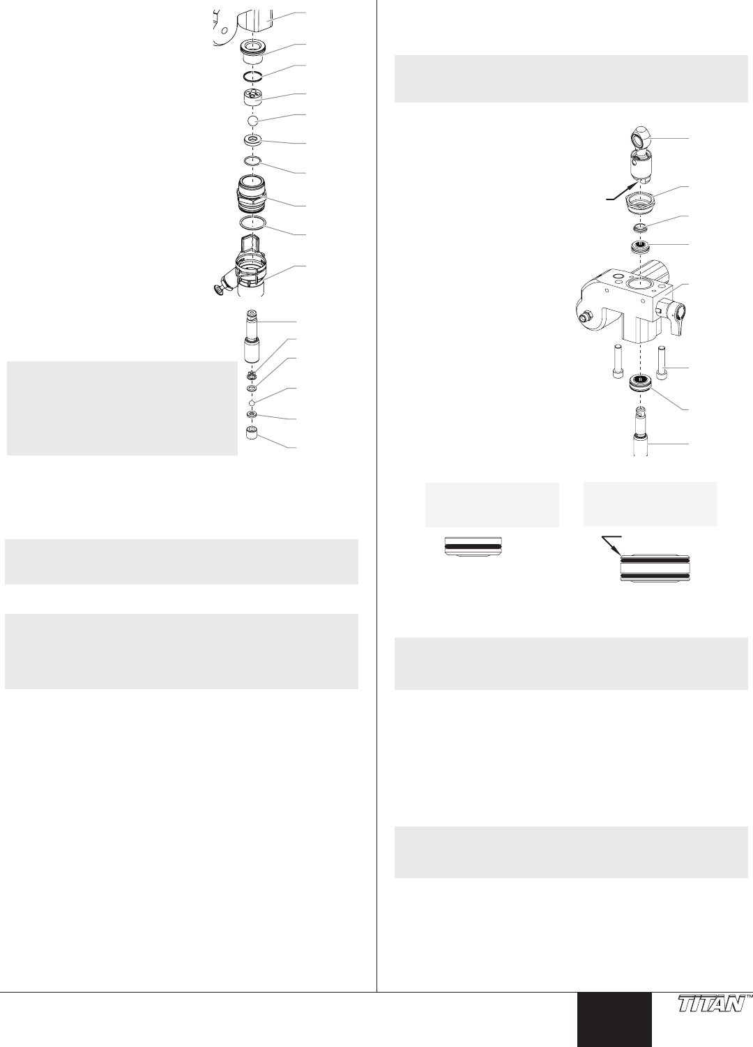
Pump
block
Bushing
Foot valv
ball
Foot valv
seat
PTFE
O-ring
Foot valv
O-ring
Foot valv
seal
Inlet cage
Pusher
stem
Servicing the Valves
The design of the uid section allows
access to the foot valve and seat as well
as the outlet valve and seat without
completely disassembling the uid
section. It is possible that the valves
may not seat properly because of
debris stuck in the foot valve seat or
outlet valve seat. Use the following
instructions to clean the valves and
reverse or replace the seats.
1. Remove the pusher stem clip
and slide the pusher stem
housing from the foot valve
housing.
2. Using a wrench, loosen and
remove the foot valve housing
from the pump block.
3. Clean out any debris in the foot
valve housing and examine
the valve housing and seat. If
the seat is damaged, reverse or
replace the seat.
Outlet valv
Outlet valv
seat
Outlet valv
ball
Outlet cage
Crush
washer
Piston rod
4. Using a 5/16” hex wrench, loosen and
remove the outlet valve retainer from
the piston rod.
NOTE: Always service the outlet valve
with the piston rod attached
to the pump. This will prevent
the piston rod from rotating
during disassembly of the
outlet valve.
5. Clean out any debris and examine the
outlet valve housing and seat. If the seat is damaged, reverse
or replace the seat.
6. Remove, clean, and inspect the outlet cage, crush washer, and
outlet valve ball. Replace if they are worn or damaged.
NOTE: The outlet cage always must be used with the crush
washer. They are included together in the repacking
kit as assembly P/N 704-642.
7. Reassemble the valves by reversing the steps above.
NOTE: During reassembly of the outlet valve, apply one
drop of Loctite (included in the repacking kit) to the
threads of the outlet valve retainer before threading
it into the piston rod. Then, torque the retainer to
144 in./lbs. (12 ft./lbs.).
Repacking the Fluid Section
1. Remove the foot valve assembly using the steps in the
“Servicing the Valves” procedure above.
NOTE: The outlet valve does not need to be disassembled
from the piston rod for this procedure.
Slider
assembly
Retainer
nut
Piston
guide
Upper
packing
Pump
block
Lower
packing
Pump bloc
mounting
screw
Piston rod
-Slot
2. Using 3/8” a hex wrench,
loosen and remove
the two pump block
mounting screws.
3. Pull the pump block down
approximately 1/2” from
the pump housing.
4. Slide the pump block and
piston rod forward until
the piston rod is out of
the T-slot on the slider
assembly.
5. Slide the piston rod out
through the bottom of
the pump block.
6. Loosen and remove the
retainer nut and piston
guide from the pump
block.
7. Remove the upper and
lower packings from the
pump block.
8. Clean the pump block and
install the new upper and
lower packings. Refer to
the illustration below for proper packing orientation.
Install upper packing
with raised lip and O-ring
facing down.
O-Ring
Raised Lip
Beveled Edge
Install lower packing
with the beveled
edge facing up.
9. Inspect the piston rod for wear and replace if necessary.
10. Reassemble the outlet valve assembly into the piston rod.
Tighten the outlet valve retainer with a wrench until secure.
NOTE: Use the T-slot on the slider assembly to hold the
piston rod in position while securing the outlet valve
retainer.
IMPORTANT: Never use a wrench on the piston itself. This could
cause damage to the piston and cause leakage.
11. Insert the piston guide into the retainer nut. Thread the
retainer nut into the pump block until it is hand tight.
12. Slide the piston guide tool (included in the repacking kit) over
the top of the piston rod and insert the piston rod through
the bottom of the pump block. Using a rubber mallet, tap
the bottom of the piston rod lightly until the piston rod is in
position in the pump block.
NOTE: Coat the piston guide tool and the piston rod with
grease before inserting them into the pump block.
13. Using a wrench, tighten the retainer nut securely.
14. Slide the top of the piston rod into the T-slot on the slider
assembly.
15. Position the pump block underneath the pump housing and
push up until it rests against the pump housing.
16. Thread the pump block mounting screws through the pump
block and into the pump housing. Tighten securely.


