2/2
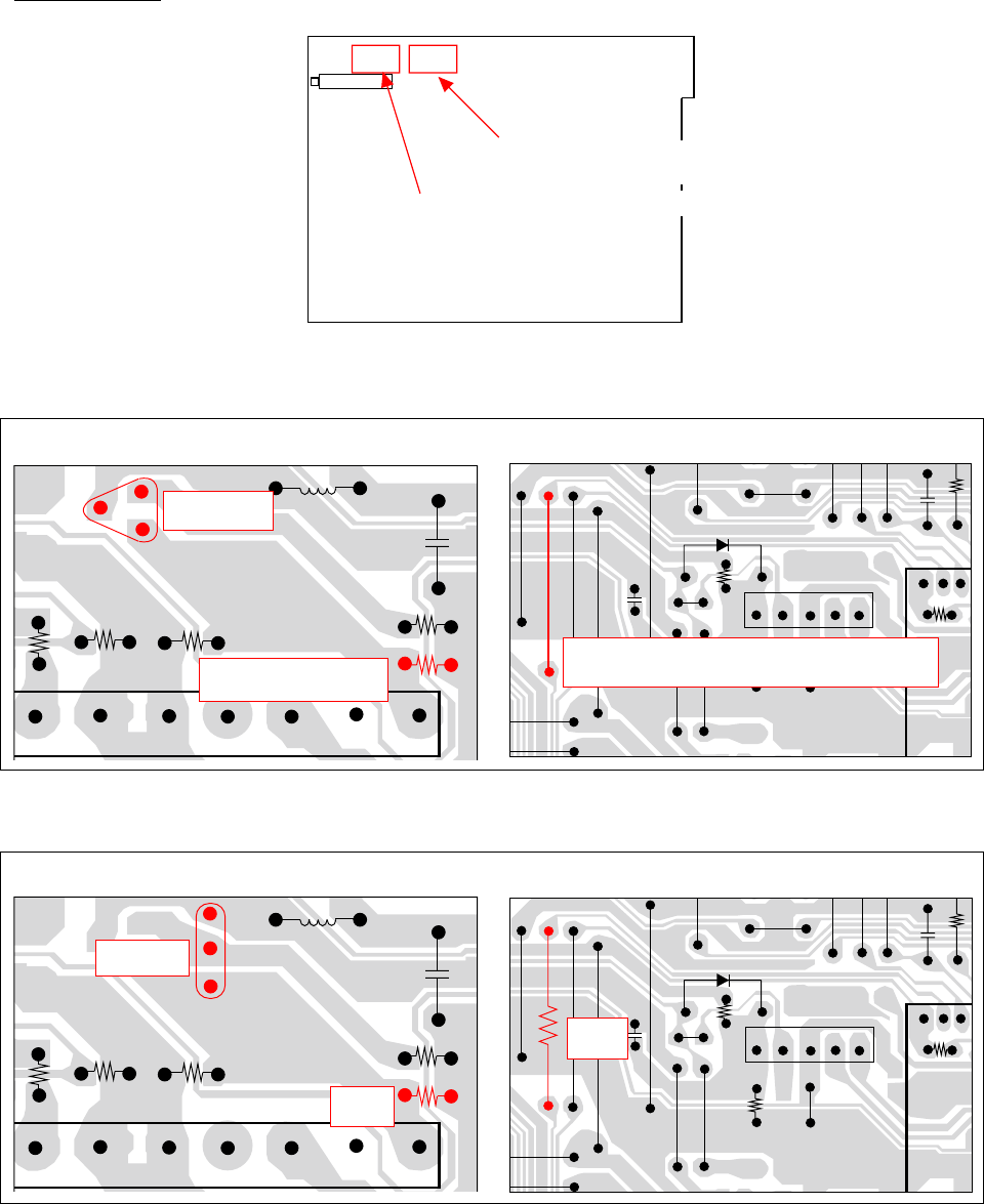
Wiring diagram
Circuit 1
Tuner block The line of Pin34 of IC301.(SAND)
Circuit 2
Tuner block The line of Pin34 of IC301(SAND)
<NOTE>
The improper use of spare parts will be cause of the beat noise on Aerial.
−ΩWhen the buzz noise arises on Aerial or line input of TV F21T1(Circuit 1), mount the 27K
instead of JW197.
57 11
Q103
2SC27140
R107
1KΩ(TV
−
F21T1:1.5KΩ
TU101
135
FL201
IC301
34
JW197
Jumper wire(TV
−
FA2110/TV
−
FA21T2:27KΩ)
57 11
R107
Q101
2SC3779
1.5KΩ
135
FL201
IC301
34
JW197
27KΩ
TU101
REAR
FRONT
Wiring diagram(MAIN C.B)
Location of modifidation for the Tuner block.
Location of modification for the line
of Pin34 of IC301(SAND)


