


Copyright 2002 © Alpine Electronics of America, Inc. REV. A-101502
ToggleToggle
dB
MODE MODE
ENT
ENT
ENT
ENT
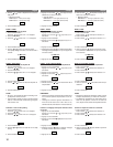
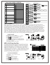
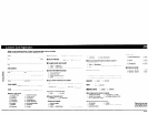
• Push "MODE" to access "1" (INPUT).
• Push "ENT" enter "1". Push "ENT" to enter "1-1" (SELECT).
• Toggle to select "1ch" or "2ch". Push "ENT".
• Push "ENT" to enter "1-2" (INPUT LEVEL).
• Toggle to the input level that will properly match the
source unit output to the amplifier input. Severely clipping the
input will result in high distortion, so use the clipping indicator
as a guide to set this level.
• Press "MODE" to advance to step 2 below.
SETTING THE INPUT
START HERE
T
O
S
T
E
P
2
Toggle Toggle
MODE
ENTENT
Hz
ENT ENT
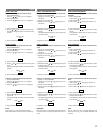
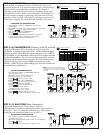
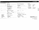
• You should be in mode "2" (LPF) now from the
previous step.
• Push "ENT" to enter "2".
• Push "ENT" to enter "2-1" (ON/OFF).
• Toggle to "ON". Push "ENT".
• Push "ENT" to enter "2-2" (FREQUENCY).
• Toggle to desired frequency.
• Push "MODE" to advance to step 3 below.
ADJUSTING THE CROSSOVER
START HERE
T
O
S
T
E
P
3
STEP 1. (1) INPUT
INPUT menu setup is critical for achieving a proper signal match with your source while minimizing distortion.
INPUT SELECT (mode 1-1) determines how many signal connections to the amplifier are made. If you are running
one channel (one mono RCA connection), set the amplifier’s input mode to “1ch”, and plug the RCA into the
left/white signal input. If you are running a stereo bass signal to the amplifier (both left and right channel RCA’s),
set the amplifier’s input mode to “2ch”, and plug both RCA connectors into the appropriate jack. INPUT LEVEL
(mode 1-2) allows the A/D converter’s input signal range to be optimized for the best possible signal clarity and
output level. Setting this overly sensitive (severely clipping the input) can result in very high distortion with musical
peaks, so use the clipping indicator as an additional guide in setting this level. If additional gain is still required,
return to this adjustment again later after continuing through the remaining setup steps.
STEP 2. (2) LPF (Low Pass filter)
Eliminating unwanted higher frequencies is essential for optimizing
subwoofer performance and integration with the rest of the system.
Selecting the appropriate cut off frequency of the low pass filter will
depend upon the application, so a wide frequency range (30Hz-
200Hz) is provided to choose from. Please note however, that if the
selected frequency is very close to or overlaps with the subsonic filter,
it will result in little or no output. Also, if an external crossover is
used, the internal filter can be turned off.
Lower Frequency (LP) Higher Frequency
1
0dB
20 30 40 60
80
100K 1000K10Hz
80Hz Sample Adjustment
1
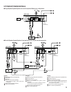
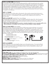
MODE SELECT FUNCTION SELECT
2
1–1 1–2
MODE ENT
2–1 2–2
3
3–1 3–2
4
4–1 4–2 4–3 4–4
5
5–1
6
6–1 6–2
7
7–1
8
8–1 8–2
9
9–1
0
0–1 0–2
1
BUTTON
FLOW
(DOWN) (UP)
MODE FUNCTION
No.
1
2
3
4
5
6
7
8
9
0
No.
1-1
1-2
2-1
2-2
3-1
3-2
4-1
4-2
4-3
4-4
5-1
6-1
6-2
7-1
8-1
8-2
9-1
0-1
0-2
Contents
INPUT MODE
LPF
SUBSONIC
PARAMETRIC EQ
BASS COMP.
TIME CORR.
PHASE
AMP SET
SAFE MODE
MEMORY
Contents
SELECT
INPUT LEVEL
ON/OFF
FREQUENCY
ON/OFF
FREQUENCY
ON/OFF
FREQUENCY
WIDTH (Q)
LEVEL
ON/OFF
ON/OFF
DELAY TIME
0/180
ID No.
TURN ON DELAY
ON/OFF
WRITE
READ
Tables related to MODE and FUNCTION