


CV7 Touch Panel Accessories
20
7" Modero Widescreen Touch Panels
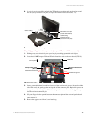
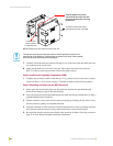
7. Carefully lift-off the back box housing and angle it over to the side of the unit where the wires
are connected to the circuit board.
8. Gently lay the back box to one side of the unit. This exposes the internal circuit board
(FIG. 21). Take care not to place undue strain on the speaker cables.
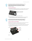
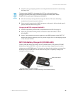
Step 2: Installing the Upgrade Components (NXD)
1. Complete the procedures outline within the Step 2: Upgrading internal components (Compact
Flash and Wireless cards) section on page 17 and then continue with the following Step 3.
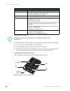
Step 3: Replacing and Securing the NXD Enclosure
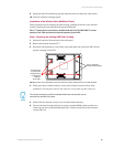
1. Gently place the outer housing back onto the panel and align the four pan-head Housing
Screws holes along the edges of the outer housing.
2. Insert and secure the four pan-head Housing Screws back into their pre-drilled holes by using a
grounded Phillips-head screwdriver.
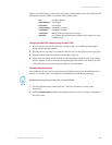
3. Slip the connector overlay back into the connector opening by inserting the top of the overlay
into the connector opening in an upwards direction.
4. Align the connectors to their respective locations and secure the overlay by pushing it towards
the connectors until the overlay securely snaps back into the overlay release latches.
5. Re-install the faceplate onto the panel. Refer to the Installing the Button Trim Ring section on
page 31 for more detailed faceplate installation information.
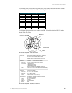
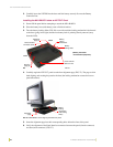
FIG. 21 Removing the rear back box from the main unit
Caution: Speaker wires come
connected to this side of the main
board. Use caution when removing
the back box.
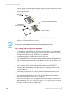
Compact Card
Slot #1 located
on the bottom slot
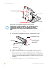
Connector Overlay must first be
removed from the side of the NXD
The internal circuit board comes pre-wired to internal speakers located on the
internal side of the back box. If the back box is removed incorrectly, these speaker
wires can become disconnected and damaged.