


3
Instruction Manual
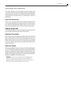
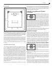
Subwoofer Rear Panel
RIGHT
+
-
L/MONO
-
+
OUTPUT
HIGH
LEVEL
INPUT
STDBY
RIGHT
L/MONO
LOW
LEVEL
LOWPASS
BYPASS
AUTOOFF ON
NORMAL
1800
FREQ
PHASE
LEVEL
16050
MAXMIN
STATUS
220-240V
RISK OF ELECTRIC SHOCK
DO NOT OPEN
110-120V
POWER
CAUTION
WARNING
ON OFF
TO REDUCE THE RISK OF FIRE OR ELECTRIC SHOCK, DO NOT EXPOSE
THIS APPLICANCE TO RAIN OR MOISTURE. NO USER SERVICEABLE
PARTS INSIDE. REFER SERVICING TO QUALIFIED SERVICE PERSONNEL
WARNING: SHOCK HAZARD-DO NOT OPEN
AVIS:RISQUE DE CHOC ELECTRIQUE-NE PAS OUVRIR
FUSE 115,T2AL/250V
FUST 230V,T1.25AL/250V
110-120VAC~60Hz
220-240VAC~50Hz
180WATTS
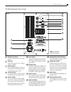
Variable Level Control
Use this control to set the level of bass
desired
Status LED
This will be green for "on" condition,
amber for "standby"
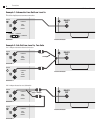
Low Level Input
This is the preferred input to connect to
the subwoofer or LFE line out from your
receiver/processor. (pgs 5 and 6)
Low Pass Control
An adjustable (40Hz to 140Hz) @ 18dB/
octave low-pass crossover. (pgs 5 and 9)
Low Pass Switch
When in the NORMAL position, adjust-
ment of the crossover can be made by
the Crossover Control. If being fed a pre-
filtered or THX signal, place the switch at
the BYPASS position. (pgs 5 and 9)
Phase Control
This switch allows precise acoustic
matching with satellite speaker systems
whose output may be phase reversed.
(pgs 5 and 10)
Standby Switch
When in ON position, the amplifier will
always be on. When in the AUTO posi
-
tion, the amplifier will be in Automatic
Standby Mode. When in the OFF position,
the amplifier is muted. (pages 5 and 9)
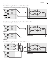
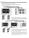
High Level Input
Use this input if your receiver/processor
lacks a line-level output, or if you have
some other reason to do so. (pgs 5 and 8)
High Level Output
If using the high level input, you may con-
nect your right and left satellites here. This
output has a high-pass filter to help avoid
overdriving of satellites. (pgs 5 and 8)
Product Model and Serial Number
Write this number in the space provided
on page 2 for future reference.
Voltage Select Switch
Voltage switch for use in different coun-
tries. This switch will be set when you
receive the unit. Change this setting
only when you are sure your application
requires it. For US, the switch should be
set to the 110-120V position.
On/Off Switch
Use this switch to turn the amplifier com-
pletely on or off.
AC Input and Fuse Holder
Use the included power cord to connect
your amplifier to a wall outlet. (pgs 5
and 6)
1
4
3
2
10
8
9
10 CSB Subwoofer Rear Panel
Figure 1
8
13
7
5
12
11
6
11
12
10
1
2
4
5
7
9
3
13
6
NOTE:
Your amplifier's
appearance may differ
slightly from illustration