


Installation Overview
ATTENTION:
• Installation and service must be performed by authorized personnel only.
• L’installation et l’entretien doivent être effectués par le personnel autorisé
uniquement.
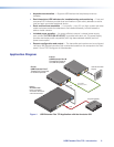
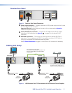
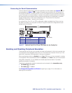
To ensure proper operation, the transmitter, receiver, USB host, and USB peripherals must
be connected properly and in the sequence described below (see figure 4 on the previous
page).
1. Power off the USB host computer connected to the transmitter and all devices that will
be directly connected to the receiver.
2. If desired, choose a location and mount the transmitter and receiver (see the
instructions for the selected mounting option for the mounting procedure).
• If rack mounting, fasten the enclosure to the rack or rack shelf.
• If furniture mounting, install the mounting brackets (not included), then fasten the
brackets to the furniture.
• For table mounting, attached the provided four rubber feet to the bottom of the unit
and place it where desired.
3. Connect a CATx twisted pair cable to the RJ-45 Output port of the transmitter and the
Input port of the receiver.
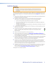
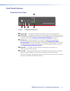
4. Connect the external power supplies (provided) to the transmitter and to the
receiver. The green power LEDs (shown at right) on the front panels of both
extenders light.
5. Power on the host computer if you have not done so.
6. Pair the transmitter with the receiver (see Pairing the Transmitter and Receiver on
the next page). When the pairing process is complete, the Link LEDs on the front panels
of the transmitter and receiver light.
7. Connect a USB Type A-B cable from a USB port of the host computer to the transmitter
Host port. Shortly after, the Host LED on the receiver starts blinking, indicating that
communication between the USB and host has been established.
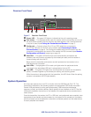
8. Connect up to four USB peripheral devices (such as a keyboard, mouse, scanner, or
printer) to the receiver Hub ports. When the first device is connected, the Host LED
stops blinking and remains lit steadily. As each peripheral device is connected, the LED
for its hub port lights when the host PC detects the device.
9. If desired, connect a 9-pin D-to-2.5 mm TRS cable between a computer and the front
panel Config port on the transmitter, receiver, or both to configure the units via SIS
commands (see Connecting for Serial Communication on page 8).
The system is now ready to operate.
USB Extender Plus T/R • Installation and Operation 6